
Method of adjusting filter parameters and an associated playback system

Inactive Publication Date: 2008-08-05
ROBERT BOSCH GMBH
View PDF7 Cites 6 Cited by
  • Summary
  • Abstract
  • Description
  • Claims
  • Application Information

AI Technical Summary

Benefits of technology

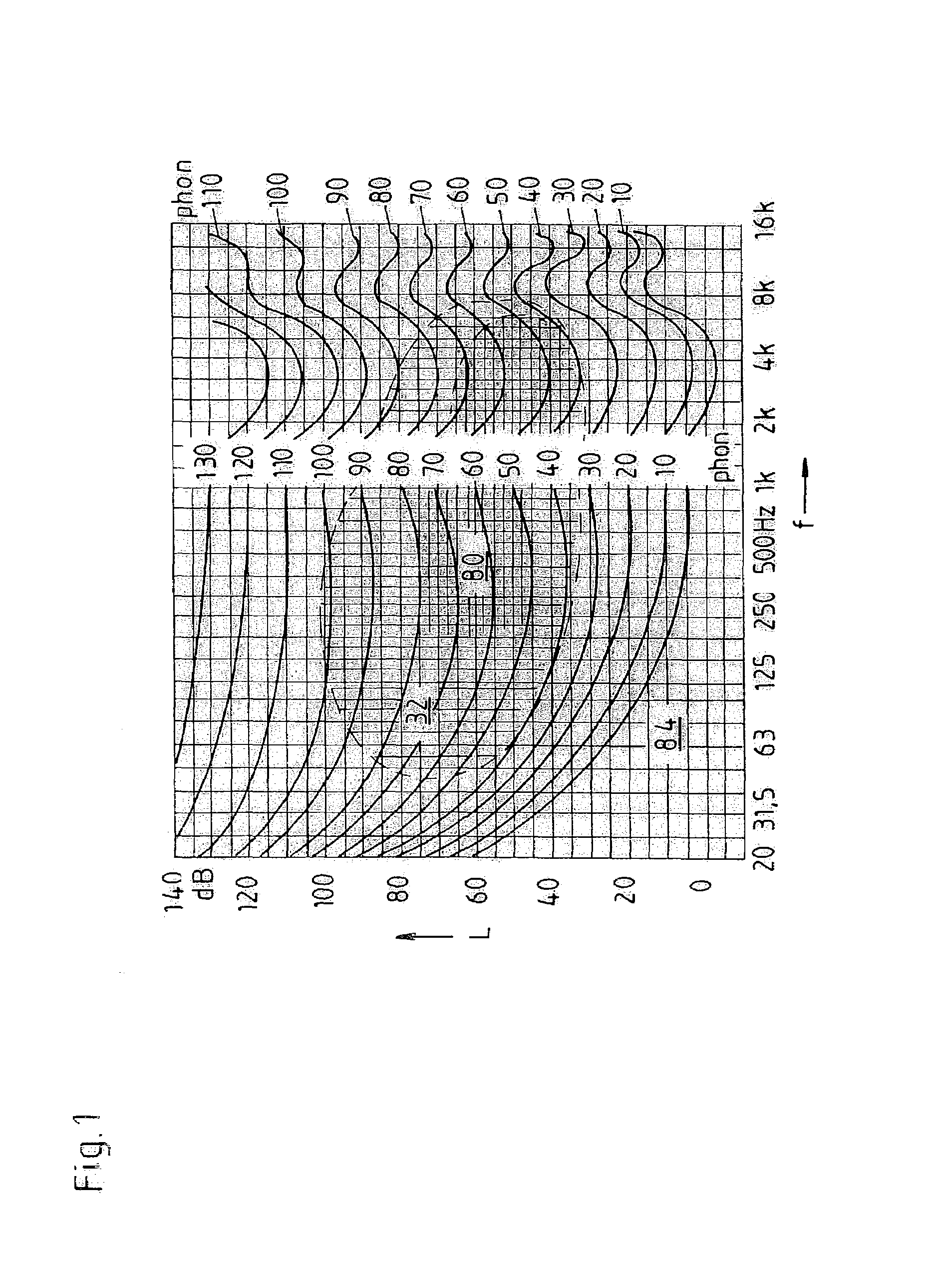
[0023]According to the present invention, an automatic optimization of the loudness of the audio playback system is achieved. In the method according to the present invention, this is associated with automatic optimization of the acoustically correct boosting of the bass in the playback system and is implemented by a calibration method which determines the efficiency of the audio playback system as a function of audio frequency and thus optimizes the loudness characteristic in the playback system so the best possible frequency response correction may be performed as a function of the performance of the playback system.
[0028]The present invention thus relieves the user of the difficult task of adjusting the filter unit(s) to the specific acoustics of the interior of his / her vehicle. In this connection, measuring the amplitude response and / or frequency response not only makes it possible to adjust n−1 equalizer filters but also makes it possible to adjust a loudness filter in the lower frequency range—as a surprising byproduct which could not be foreseen by those skilled in the art—assuming a total of n second-order recursive filters in the playback system as an example. In this connection, the loudness filter is one of the resonance filters, or in more general terms, one of the n second-order recursive filters (under certain conditions, the recursive filter may also be designed as a shelving filter, but this is not the norm in the case of the present invention).
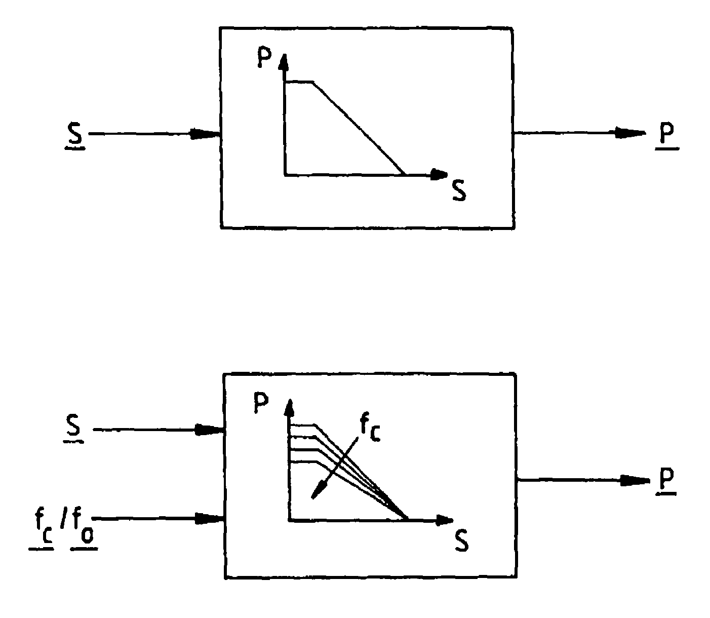
[0037]The feature whereby the filter parameter(s) of the filter unit is / are adjusted automatically so that the mid-frequency of the filter unit is just above the cutoff frequency determined may be associated with the feature whereby the boosting of the bass level is reduced with an increase in cutoff frequency and / or mid-frequency of the filter unit, so that the isophones in the remaining reproducible bass frequency range are not exceeded (→functional relationship between the filter mid-frequency / cutoff frequency and the loudness setting as input variables and the resulting bass boosting as an output variable. This functional relationship is based on a mathematical function and may be accomplished continuously or in stages, depending on the particular givens. Thus, as a result, automatic optimization of an acoustically correct bass level boosting is achieved by adjusting the filter parameters of the bass-boosting filter unit as a function of the cutoff frequency and / or the mid-frequency).
[0038]In this way, acoustically correct bass level boosting is automatically optimized in a synergistic manner while at the same time excessive boosting of the bass level is prevented. It has also been found according to the present invention that acoustically correct bass level boosting may be optimized using the control processor of the car radio device, which is present anyway, with the help of appropriate additional software.
[0039]Thus, as a result, no additional audio module having a digital signal processor is necessary with the present invention, but instead this requires only a microphone circuit, an amplifier circuit and a rectifier circuit, which are connected to the AD (analog / digital) converter unit present in the control processor. Therefore, only a very small increased complexity in terms of hardware and software and therefore a small increased cost are necessary for automatic adjustment of the filter parameters with respect to the mid-frequency as proposed according to the present invention.
[0042]From the standpoint of minimizing hardware and software complexity, it has proven advantageous for the bandpass noise signals for determining the acoustic frequency response of the interior of the vehicle to be generated with the help of the equalizer itself which is to be adjusted.

Problems solved by technology

However, in the case of known loudness functions, the choice of an optimum use frequency for boosting the bass level poses a problem.
However, this is not appropriate in all audio playback systems, because the performance of certain amplifiers and / or loudspeakers potentially does not allow playback of extremely low frequencies.
Greater boosting at very low frequencies would thus have no acoustic effect and might under some circumstances even result in overloading the amplifier stages and / or loudspeakers.
If the performance of the amplifier stages and / or loudspeakers is not known by the control unit responsible for the loudness, which is typically the case in a system having a “car radio booster loudspeaker,” the adjustment of the loudness characteristic at the factory may not always be optimal.
Manual adjustment of the loudness characteristic by the user, however, requires a certain amount of acoustic and technical knowhow.
In particular, such a manual adjustment proves problematical in practice inasmuch as the user must be very familiar with the acoustics of his vehicular device to make an optimum adjustment of the equalizer, and it is very difficult to determine the acoustic frequency response without the help of measurement technology, i.e., merely by listening.
The operating instructions of known car radio equipment may provide only very limited assistance in making the best possible adjustment of the equalizers, because these operating instructions are by no means able to take into account all makes and models of vehicles, let alone the multitude of individual equipment options and amplifier and loudspeaker configurations.
Use of a graphic equalizer to optimize the acoustically correct boosting of the bass level has proven to be problematical in practice with respect to the acoustics of the interior of a vehicle.
Thus, narrow resonance overshooting in the acoustic frequency response of the interior of the vehicle between the equalizer bands will not be optimally compensated.
Furthermore, the additional audio module having the digital signal processor for implementing the graphic equalizer and for calibration of this equalizer are relatively cost intensive.

Method used


Image

  • Method of adjusting filter parameters and an associated playback system
  • Method of adjusting filter parameters and an associated playback system
  • Method of adjusting filter parameters and an associated playback system

Examples


Embodiment Construction

[0050]Audio playback system 100 illustrated in FIG. 3 is used for playback of audio signals in the interior of a motor vehicle, the audio signals being generated by various audio sources 10, 12 such as a CD (compact disc), a radio or the like.

[0051]Playback system 100 has a loudspeaker device 50 and an audio processor 20 situated in the signal path between audio sources 10, 12 and loudspeaker device 50, this processor having two freely adjustable digital equalizers 22, 24 by which the signals of different audio sources 10, 12 may be sent to loudspeaker device 50. More than two equalizers 22, 24 may of course also be provided here. For adjusting the filter parameters, in particular for adjusting the mid-frequency, a control processor 30 sends suitable filter parameters to audio processor 20 via a control bus 34.

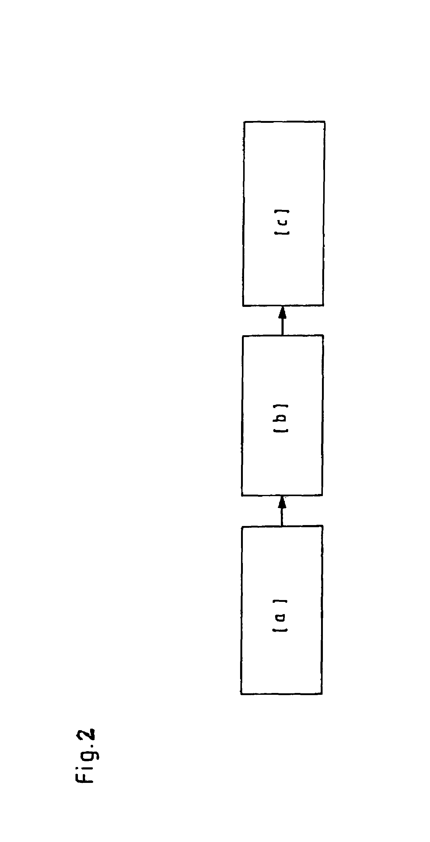
[0052]For determining and / or measuring the frequency response of the present audio system in the interior of a vehicle (=method step [a] according to FIG. 2), playback system ...


PUM


Abstract

To improve upon a method of adjusting at least one filter parameter such as the mid-frequency of at least one filter unit provided with a playback system for audio signals, this filter unit being provided in particular for at least one digital equalizer assigned to the playback system, as well as an associated playback system so as to achieve automatic optimization of an acoustically correct bass level boosting,[a] first the acoustic frequency response is determined,[b] then a cutoff frequency below which the sound pressure falls below a sound pressure threshold level based on the average sound pressure is determined, and[c] next the filter parameter(s) of the filter unit is / are adjusted automatically, so that the mid-frequency of the filter unit is just above the cutoff frequency thus determined.

Description

FIELD OF THE INVENTION[0001]The present invention relates to a method of adjusting at least one filter parameter such as the mid-frequency, of at least one filter unit provided for a playback system for audio signals, in particular a second-order recursive filter unit or a resonance filter unit, which is associated in particular with at least one digital equalizer provided with the playback system.[0002]The present invention also relates to a playback system for audio signals, in particular for performing a method of the type described above, which is provided for adjusting at least one filter parameter, such as the mid-frequency of at least one filter unit associated with the playback system, in particular to at least one digital equalizer provided for the playback system,[0003]having at least one loudspeaker device and[0004]having at least one audio processor which contains the equalizer and[0005]situated in the signal path between at least one signal source and the loudspeaker de...

Claims


Application Information

Patent Timeline
IPC IPC(8): H03G5/00H03G3/00H03G7/00H04B1/00H04R29/00H03H21/00H04R3/00
CPCH03G5/005H04R3/002H03H21/0012H03G5/165
Inventor MONTAG, CHRISTOPHSAHRHAGE, JOERG
Owner ROBERT BOSCH GMBH
Learn More