Methods for producing three dimensional, self-supporting, light redirecting roof lighting systems

a roof lighting system and self-supporting technology, applied in the direction of roof coverings, lighting and heating equipment, building components, etc., can solve the problems of reducing the transmission of high-angle light through the roof lighting system to the room below, holograms and diffraction gratings produced photographically tend to degrade in sunlight, and deficient use of holographic or diffractive light redirecting plates

Inactive Publication Date: 2008-08-12
EDMONDS IAN ROBERT
View PDF10 Cites 23 Cited by
  • Summary
  • Abstract
  • Description
  • Claims
  • Application Information

AI Technical Summary

Problems solved by technology

The use of holographic or diffractive light redirecting plates is deficient in that holograms and diffraction gratings redirect light by interference and are therefore intrinsically dispersive producing a coloured effect to transmitted light.
Also holograms and diffraction gratings produced photographically tend to degrade in sunlight.
This reduces the transmission of high angle light through the roof lighting system to the room below.
However the cutting and assembly cost is prohibitive for smaller roof lighting systems of the type associated with light pipes and for light redirection systems for use with electrical lights such as light bulbs and fluorescent tubes.

Method used


Image

  • Methods for producing three dimensional, self-supporting, light redirecting roof lighting systems
  • Methods for producing three dimensional, self-supporting, light redirecting roof lighting systems
  • Methods for producing three dimensional, self-supporting, light redirecting roof lighting systems

Examples


Embodiment Construction

.

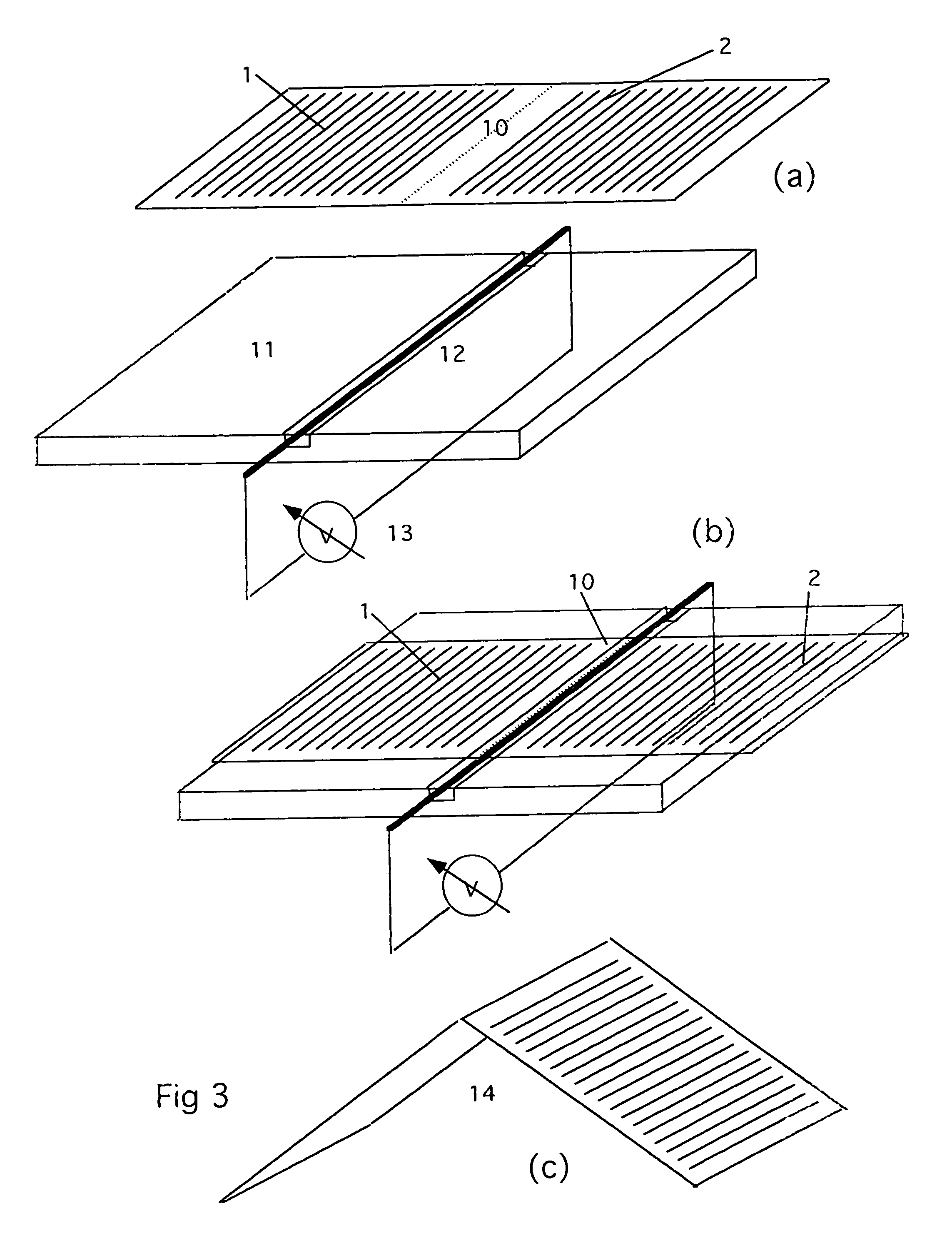
[0018]The first method of this invention is illustrated by the method for producing the simplest geometrical form of angle selective roof lighting system, that is, a saddle form of angle-selective lighting system. The method is described with reference to FIG. 3. FIG. 3 (a) shows a flat rectangular transparent acrylic sheet with two arrays of parallel laser cuts 1 and 2 made through two sections of the flat sheet. A narrow strip of solid plastic 10 is left between the two arrays of laser cuts 1 and 2. The laser cuts may penetrate right through the sheet, or, may be cut partly through the sheet so that one side of the sheet remains solid. Typical depth of the laser cuts would be 6 mm and the typical spacing between each laser cut in each array of parallel cuts would be in the range 3 mm to 4 mm. If the 6 mm deep cuts were made partly through a 10 mm thick sheet of acrylic then 4 mm of the sheet would remain solid and would provide one solid, non-permeable surface to the laser cut sh...


PUM

PropertyMeasurementUnit
depthaaaaaaaaaa
depthaaaaaaaaaa
thickaaaaaaaaaa

Abstract

A self-supporting roof lighting system that accepts low elevation light and rejects high elevation light may be produced by making arrays of parallel laser cuts through, or partly through, a flat sheet of transparent acrylic, cutting the segment containing the arrays from the sheet, positioning the segment over linear heating elements to soften the acrylic along the lines between adjoining laser cut arrays, folding the segment along the softened lines through the angle necessary to form a multi-faceted structure of saddle, pyramid or higher order form and allowing this structure to cool and solidify to produce a self-supporting angle-selective roof lighting system with an array of light redirecting laser cuts on each facet. The sequence of the method may be changed so that a saddle, pyramid or higher order structure is first formed by folding or moulding transparent acrylic and, subsequently, an array of parallel laser cuts is made in each facet of the structure to produce an angle-selective roof lighting system. A conical angle-selective roof lighting system may be produced by making concentric laser cuts through, or partly through, a disc of transparent acrylic with a segment cut out, softening the laser cut disc and moulding the disc into conical form.

Description

BACKGROUND TO THE INVENTION[0001]The basic form of roof lighting system comprises a substantially horizontal glazed input aperture in the roof, a substantially horizontal output aperture in the ceiling of the room below and a passageway with reflective interior walls that connects the two apertures. Natural light passing through the system provides natural illumination to the room below. This basic form of roof lighting system is ineffective in accepting and transmitting low elevation sunlight to the room below. The reasons for poor transmission of low elevation sunlight are: (a) The projected area of input aperture reduces as sin(E) where E is the sun elevation. (b) Low elevation sunlight suffers high reflection loss at the glazed input aperture. (c) Low elevation sunlight suffers many reflections within the reflective passageway and loses energy at each reflection. Thus natural illumination via roof lights tends to be poor in the early morning and late afternoon and in winter when...

Claims


Application Information

Patent Timeline
Patent Type & Authority Patents(United States)
IPC IPC(8): F21V7/04B26D3/08B23K26/40B29C53/06B29C53/36E04D13/03
CPCB23K26/4065B29C53/066E04D13/033B29C53/36E04D2013/0345B23K2103/42B23K2103/50
Inventor EDMONDS, IAN ROBERT
Owner EDMONDS IAN ROBERT
Why Eureka
Try Eureka