Inverter powered plasma cutting system with fixed gas flow control

a plasma cutting system and gas flow control technology, applied in plasma welding equipment, manufacturing tools, solventing equipment, etc., can solve the problems of not being able to sequentially perform all, the operation of the operator is not practical, and the construction is not without its drawbacks. , to achieve the effect of simplifying the operation, control and construction of the gas system

Active Publication Date: 2008-08-12
ILLINOIS TOOL WORKS INC
View PDF6 Cites 27 Cited by
  • Summary
  • Abstract
  • Description
  • Claims
  • Application Information

AI Technical Summary

Benefits of technology

[0009]The present invention provides a lightweight and compact plasma cutting system that overcomes the aforementioned drawbacks. The plasma cutting system includes a power source having an inverter and a non-adjustable regulator operatively connected to the power source. The inverter is configured to generate a power signal suitable for an operator selected plasma arc operating mode and the non-adjustable regulator is configured to automatically set a fixed gas flow to a plasma torch depending on a selected operating mode.

Problems solved by technology

Although such in-field adjustment of the air flow provides an operator with more precision control of the air flow rate, such a construction is not without its drawbacks.
Operator control of the air flow invariably presents the opportunity for improper setting of the air flow control, especially by inexperienced operators.
It may not be practical for the operator to sequentially perform all of the desired cutting processes and then all of the desired gouging process, or vice verse.
Suspending one process to reconfigure the power source for another process is time consuming and results in overall process inefficiency.
In addition to the inefficiency associated with the repetitive reconfiguring of the power source to deliver the appropriate power signal / air flow as dictated by the intended plasma process, the means for allowing operator control of the air flow complicates power source construction and expense.
Not only does the operator variable flow control occupy space in the interior of the power source thereby increasing the overall size of the plasma cutting device, the control must be placed on the front panel, thereby further limiting the internal configuration options.
Obviously, there are drawbacks to these systems such as enabling the possibility of unregulated air to the power source if the regulator is bypassed, and simply requiring one more apparatus to the overall system.
Providing such an operating mode further complicates the construction of the power source and increases the complexity of the device and the operation thereof.

Method used


Image

  • Inverter powered plasma cutting system with fixed gas flow control
  • Inverter powered plasma cutting system with fixed gas flow control
  • Inverter powered plasma cutting system with fixed gas flow control

Examples


Embodiment Construction

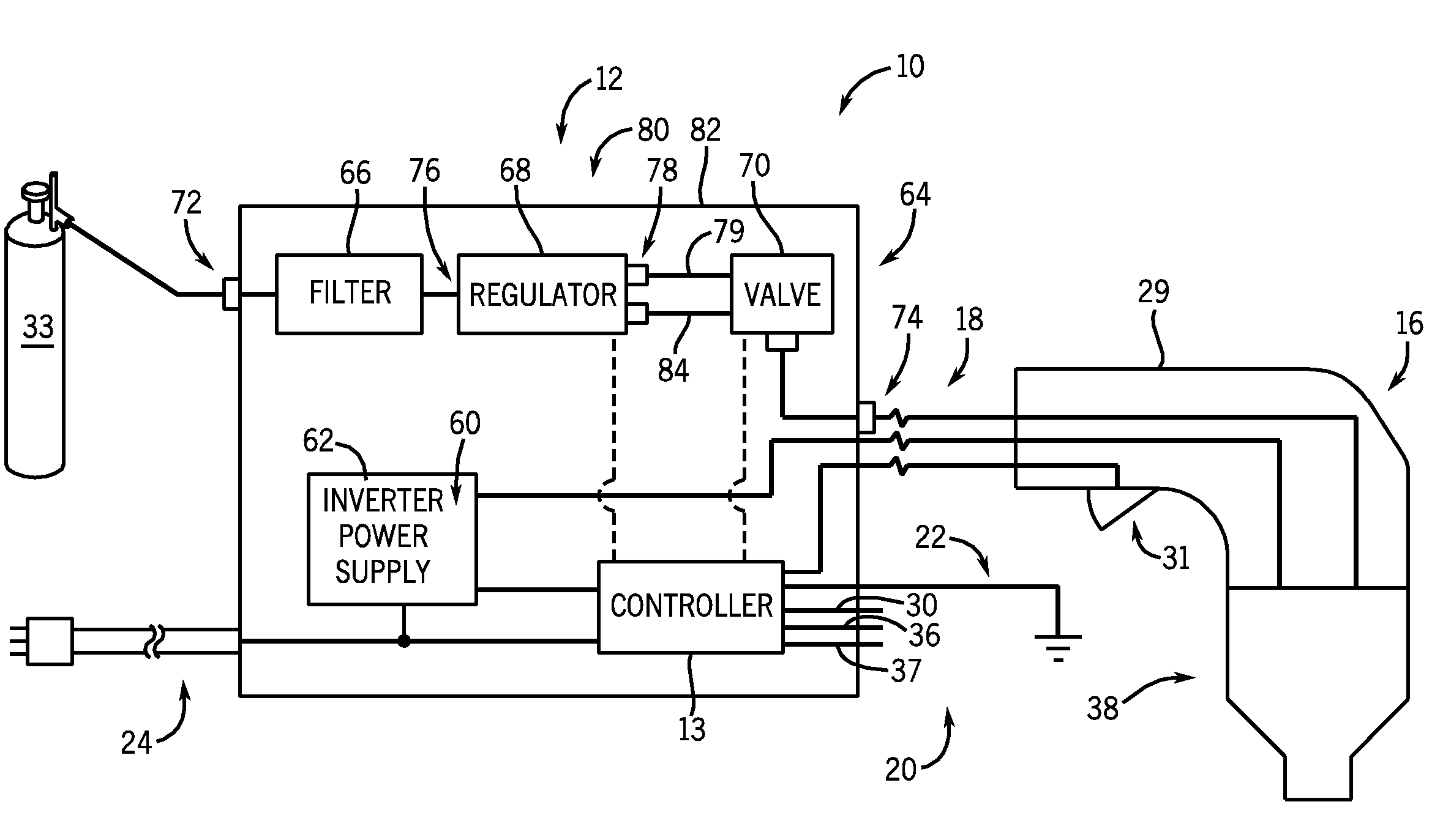
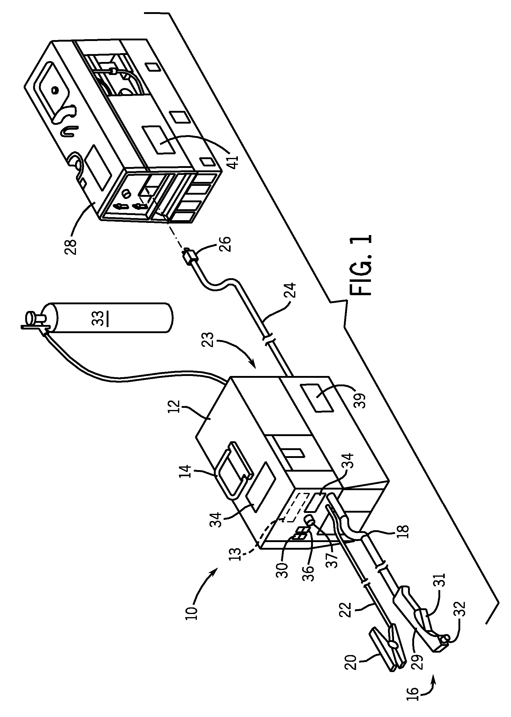
[0019]FIG. 1 shows a plasma cutting system 10 according to the present invention. Plasma cutting system 10 is a high voltage system with open circuit output voltages that typically range from approximately 230 Volts Direct Current (VDC) to over 300 VDC. Plasma cutting system 10 includes a power source 12 to condition raw power and generate a power signal suitable for plasma cutting applications. Power source 12 includes a processor / controller 13 that receives operational feedback and monitors the operation of a plasma cutting system 10. Power source 12 includes a handle 14 to effectuate transportation from one site to another. Connected to power source 12 is a torch 16 via a cable 18. Cable 18 provides torch 16 with power and compressed air or gas, and also serves as a communications link between torch 16 and power source 12. Torch 16 includes a handle portion 29, or torch body, having a trigger 31 thereon and work tip 32 extending therefrom. Although shown as attached to torch 16, ...


PUM

PropertyMeasurementUnit
voltagesaaaaaaaaaa
poweraaaaaaaaaa
plasma arc poweraaaaaaaaaa

Abstract

A lightweight and compact plasma cutting system includes a power source having an inverter and a non-adjustable regulator enclosed within the power source. The inverter is configured to generate a power signal suitable for a plasma arc process and the non-adjustable regulator is preconfigured to deliver a fixed gas flow to a plasma torch for the plasma arc process.

Description

BACKGROUND OF THE INVENTION[0001]The present invention relates generally to plasma cutting systems and, more particularly, to an inverter powered plasma cutting system with automatic gas flow control.[0002]Plasma cutting is a process in which an electric arc and plasma gas are used to cut or gouge a workpiece. Plasma cutters typically include a power source, a gas supply, such as compressed air, and a torch. The torch is constructed to create and maintain the plasma arc. To generate the plasma cutting power, a power source receives an input voltage from a transmission power receptacle or generator and provides output power to a pair of output terminals. One of the output terminals is connected to an electrode and the other is connected to the workpiece. An air supply is used with most plasma cutters to carry and propel the arc to the workpiece and assist in cooling the torch.[0003]Prior to operation of the plasma cutting system, an operator must manually set a regulator of the air f...

Claims


Application Information

Patent Timeline
Patent Type & Authority Patents(United States)
IPC IPC(8): B23K10/00
CPCB23K9/013B23K10/00B23K9/325B23K9/1006
Inventor SCHNEIDER, JOSEPH C.
Owner ILLINOIS TOOL WORKS INC
Why Eureka
Try Eureka