Focused ion beam apparatus and focused ion beam irradiation method

a focused ion beam and beam technology, applied in the direction of beam deviation/focusing by electric/magnetic means, magnetic discharge control, instruments, etc., can solve the problems of difficult to magnetically shield a sample including its neighborhood completely, difficult to prevent the separation of isotopes at the same time, and beam split into two

Active Publication Date: 2008-08-12
HITACHI HIGH-TECH CORP
View PDF25 Cites 18 Cited by
  • Summary
  • Abstract
  • Description
  • Claims
  • Application Information

AI Technical Summary

Benefits of technology

[0010]In view of the present situation of the FIB apparatus described above, it is an object of this invention to provide a focused ion beam apparatus and a focused ion beam irradiation method in which even in the case where a magnetic field exists or changes on the optical axis of an ion beam, the isotopes of the ion beam are not separated on the sample and the ion beam is focused at the beam spot position in the same manner as if a magnetic field is absent, and in the case where the FIB apparatus is combined with a SEM to make up a FIB-SEM, the sample can be microprocessed by the FIB apparatus while at the same time making it possible to observe a sample image with a high resolution under the SEM.
[0012]Especially in the case of the FIB-SEM, the primary source of the magnetic field is the objective lens of the SEM. In the narrow area in the neighborhood of the optical axis of the SEM, a downward (or upward) strong magnetic field exists, while an upward (or downward) weak magnetic field is exerted in the wide area outside the objective lens. The above mentioned effect can be produced by configuring the ion beam optics to pass through the two magnetic fields in an appropriate ratio.
[0013]For fine adjustment of the ion beam spot position, the desired magnetic field should be positively generated from a canceling magnetic field generating unit arranged on the optical beam of the ion beam. As long as the canceling magnetic field has a magnitude proportional to the external magnetic fields (including the magnetic field from the SEM objective lens of the FIB-SEM), the above-mentioned effect can be maintained against any variation in the external magnetic fields.

Problems solved by technology

Further, the normally used ion specie Ga Ga contains two types of isotopes Ga69 and Ga71 deflected to different degrees by a magnetic field, thereby posing the problem that the beam is split into two.
It is difficult, however, to magnetically shield a sample including the neighborhood thereof completely.
Although the displacement of the ion beam spot on the sample due to a magnetic field can be canceled using the electric deflector, it is impossible to prevent the separation of isotopes at the same time.
Therefore, the exit of the ion beam is very narrow, and in the presence of an external magnetic field, it is difficult for the ion beam to pass through the exit.
This problem is more serious for the FIB-SEM comprising a FIB column and a SEM column combined with each other.
In view of the fact that the ion beam is required to be radiated on a sample in the vicinity of the objective lens of the SEM, on the other hand, the optical axis of the ion beam cannot be magnetically shielded sufficiently.
Another problem is that the arrangement of a magnetic shield in the vicinity of the SEM objective lens disturbs the magnetic field of the SEM objective lens and adversely affects the resolution of the SEM.
No technique has been disclosed to solve this problem.
This residual magnetic field changes with time, thereby posing the problem that the ion beam spot also moves with time.
This method is bothersome to execute, however, in view of the need of demagnetization of the SEM objective lens each time the operation is switched from the SEM to the FIB apparatus.
With the increase in demand for a higher resolution of the SEM, however, the use of an objective lens of semi-in type has become unavoidable.

Method used


Image

  • Focused ion beam apparatus and focused ion beam irradiation method
  • Focused ion beam apparatus and focused ion beam irradiation method
  • Focused ion beam apparatus and focused ion beam irradiation method

Examples


first embodiment

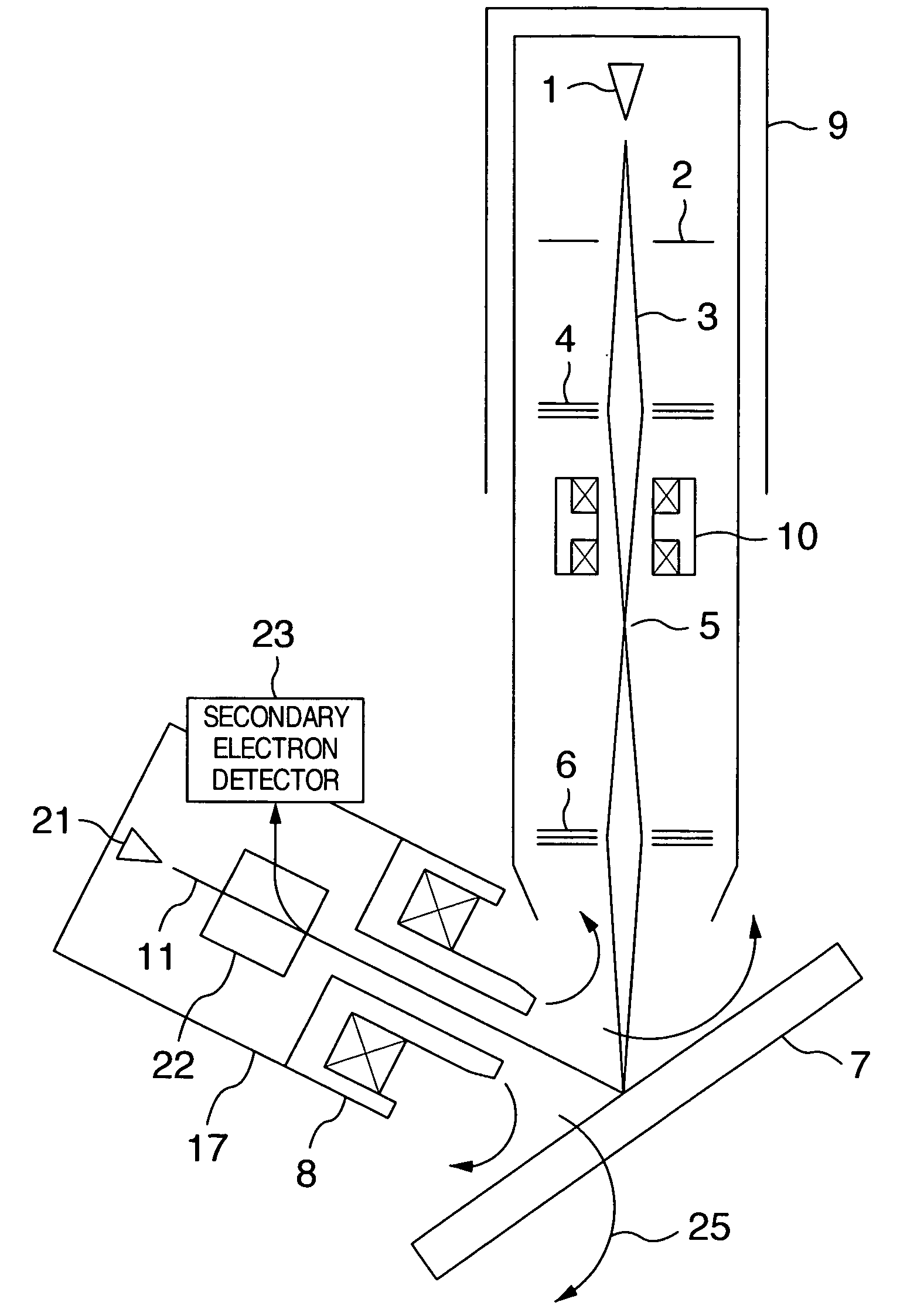
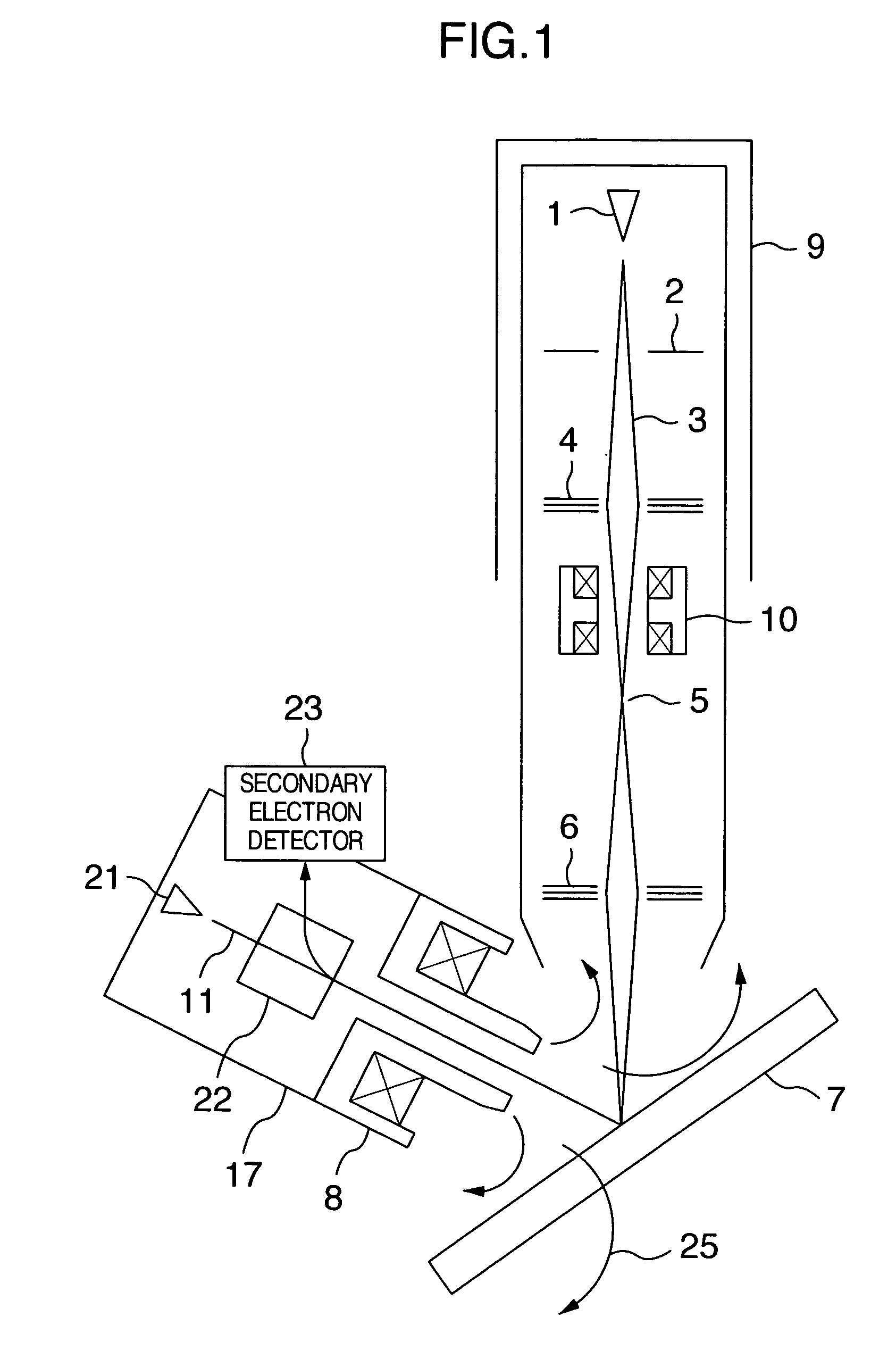
[0029]FIG. 1 is a schematic diagram showing an example of a configuration of a FIB-SEM according to the invention. The Ga ions released from a Ga liquid metal ion source 1 are accelerated by the electric field generated by an accelerating electrode 2 and formed into, for example, a Ga ion beam 3 having a kinetic energy of, say, 30 keV. The ion beam is focused at a crossover 5 by an electric condenser lens 4 (or without any cross over, focused into a substantially parallel state), and further focused on a sample 7 by an electric objective lens 6. The Ga ion beam 3 is composed of two types of isotopes, Ga69 and Ga71 having contents in the ratio of 6 to 4.

[0030]The secondary electrons generated from the sample 7 irradiated with the ion beam are detected by a detector not shown, and the image of the sample can thus be observed. A SEM 17 is used, however, for observing the image of the sample with high resolution. The electron beam 11 of the SEM 17 is generated from a cathode 21, and aft...

second embodiment

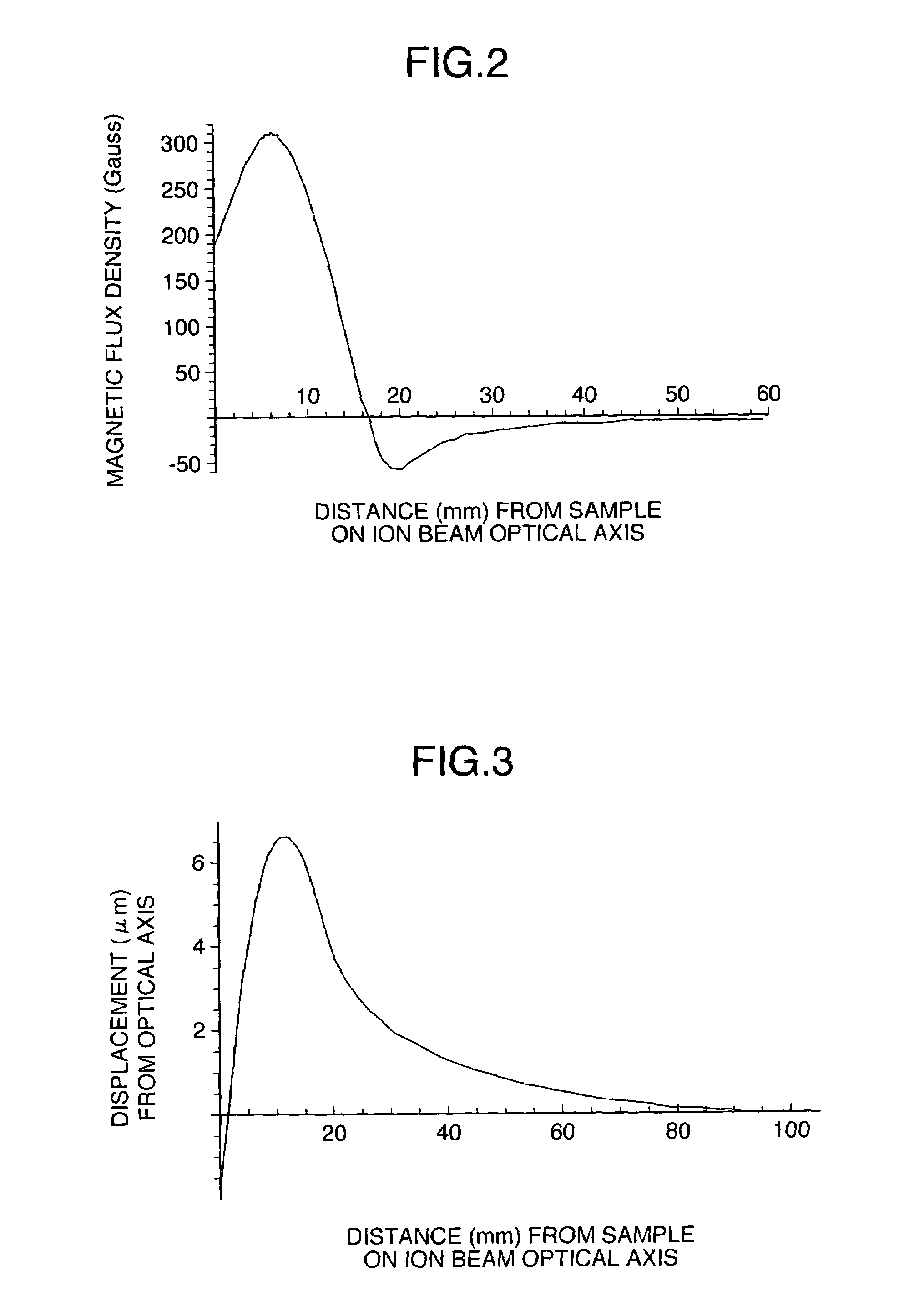
[0054]FIG. 8 is a schematic diagram showing another example of a configuration of the FIB-SEM according to the invention. Normally, the excitation of the objective lens 8 of the SEM 11 is required to be changed frequently to change the focal length or the accelerating voltage. In line with this, the magnitude of the magnetic field on the ion beam optical axis of the FIB apparatus is changed, with the result that the ion beam spot on the sample 7 is displaced and in proportion to this displacement, the isotopes are separated.

[0055]To solve the aforementioned problem, this embodiment includes a canceling magnetic field control unit 12. The canceling magnetic field control unit 12, upon receipt of a signal proportional to the exciting current of the SEM objective lens 8 from a SEM objective lens exciting current control unit 13, supplies the coil of the canceling magnetic field generator 10 with a current proportional to the particular signal. The displacement of the ion beam spot on t...

third embodiment

[0056]FIG. 9 is a schematic diagram showing another example of a configuration of the FIB-SEM according to the invention. In the case where an external magnetic field for deflecting the ion beam 3 exists in addition to the magnetic field generated by the SEM objective lens 8 and changes in magnitude, the actually existing magnetic fields are effectively measured. According to this embodiment, as shown in FIG. 9, an output of a magnetic field sensor 14 is input to the canceling magnetic field control unit 12. Although a Hall element is used as the magnetic field sensor 14 in this embodiment, any other element capable of measuring the magnetic field such as a magnetoresistive element can be used. In the case where no magnetic field is generated by the SEM objective lens 8, the canceling magnetic field control unit 12 supplies the coils of the canceling magnetic field generator 10 with a current proportional to the magnetic field measured by the magnetic field sensor 14.

[0057]Normally,...


PUM


Abstract

A focused ion beam apparatus and a focused ion beam irradiation method are disclosed. Even in the case where a magnetic field exists on the optical axis of an ion beam and the particular magnetic field undergoes a change, the ion beam is focused without separating the isotopes on the sample at the same ion beam spot position as if the magnetic field is not existent. A canceling magnetic field is generated on the optical axis of the ion beam from a canceling magnetic field generator thereby to offset the deflection of the ion beam due to the external magnetic field.

Description

BACKGROUND OF THE INVENTION[0001]1. Field of the Invention[0002]This invention relates to a technique for offsetting the deflection of an ion beam due to a geomagnetic field or a magnetic field intruding into an ion optics from another device and thus forming the ion beam spot on a sample at substantially the same position as if there is no magnetic field and a technique for avoiding the split of a beam spot which otherwise might occur in the case where the ion beam contains a plurality of types of isotopes.[0003]2. Description of the Related Art[0004]A FIB (focused ion beam) apparatus is used in practical applications to microprocess a sample or to observe an image of the sample by radiating a finely focused ion beam on the sample. The ion beam is deflected by the Lorentz force in the presence of a magnetic field on the optical axis. The accelerating voltage of the FIB apparatus is normally about several tens of kV, and therefore the beam spot may be displace several tens of μm or ...

Claims


Application Information

Patent Timeline
Patent Type & Authority Patents(United States)
IPC IPC(8): H01J1/50G21K1/093G21K7/00H01J37/08
CPCH01J37/09H01J37/3056H01J2237/31749H01J2237/0264
Inventor TAKEUCHI, KOICHIROISHITANI, TOHRUOSE, YOICHI
Owner HITACHI HIGH-TECH CORP
Why Eureka
Try Eureka