PN code generator, GOLD code generator, PN code despreader, method for generating PN code, method for generating GOLD code, method for despreading PN code and computer program

a technology of pn code and generator, which is applied in the field of pn code generator, gold code generator, pn code despreader, and method for generating pn code, which can solve the problem of large number of bits to be stored in the memory b>241/b>

Inactive Publication Date: 2008-08-12
SOCIONEXT INC
View PDF20 Cites 15 Cited by
  • Summary
  • Abstract
  • Description
  • Claims
  • Application Information

AI Technical Summary

Problems solved by technology

Consequently, when the PN code PN having a long code length (=2N−1) is to be generated, there is a problem that the number of bits to be stored in the memory 241 becomes large.

Method used


Image

  • PN code generator, GOLD code generator, PN code despreader, method for generating PN code, method for generating GOLD code, method for despreading PN code and computer program
  • PN code generator, GOLD code generator, PN code despreader, method for generating PN code, method for generating GOLD code, method for despreading PN code and computer program
  • PN code generator, GOLD code generator, PN code despreader, method for generating PN code, method for generating GOLD code, method for despreading PN code and computer program

Examples


first embodiment

[0061]At first, a first embodiment of the present invention will be described. Incidentally, the explanation is given that a PN code generator according to the present embodiment is defined as generating a PN code by a logical operation, which is the same as the PN code generated by a PN code generator of an M-sequence (Maximum-length Sequence) constituted by a linear feedback shift register of degree 4.

[0062]FIG. 5 is a schematic diagram showing the first embodiment of the present invention, in which a principle to generate the PN code generated by the linear feedback shift register of degree 4, by using the PN code generator according to the present embodiment is explained.

[0063]As shown in FIG. 5, in the PN code generator according to the present embodiment, a PN code group 50a at a first to fourth phases, among the PN code having a code length of 15 generated by the linear feedback shift register of degree 4 (output code shown in FIG. 24) is generated by performing the above-des...

second embodiment

[0111]Next, a second embodiment according to the present invention is described.

[0112]In the present embodiment, as shown in FIG. 7, shift code patterns to be stored in a code memory 11 and mask code patterns to be stored in a code mask memory 12 are stored in the same address by every N bits, so that the number of read out of the code pattern can be reduced. As stated above, N is a degree of a linear feedback shift register.

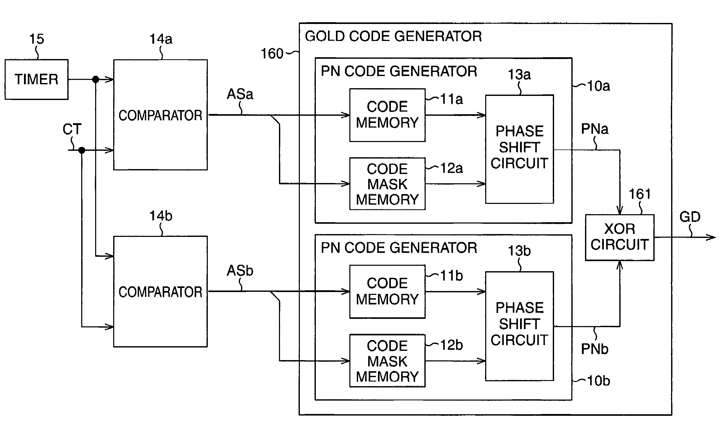
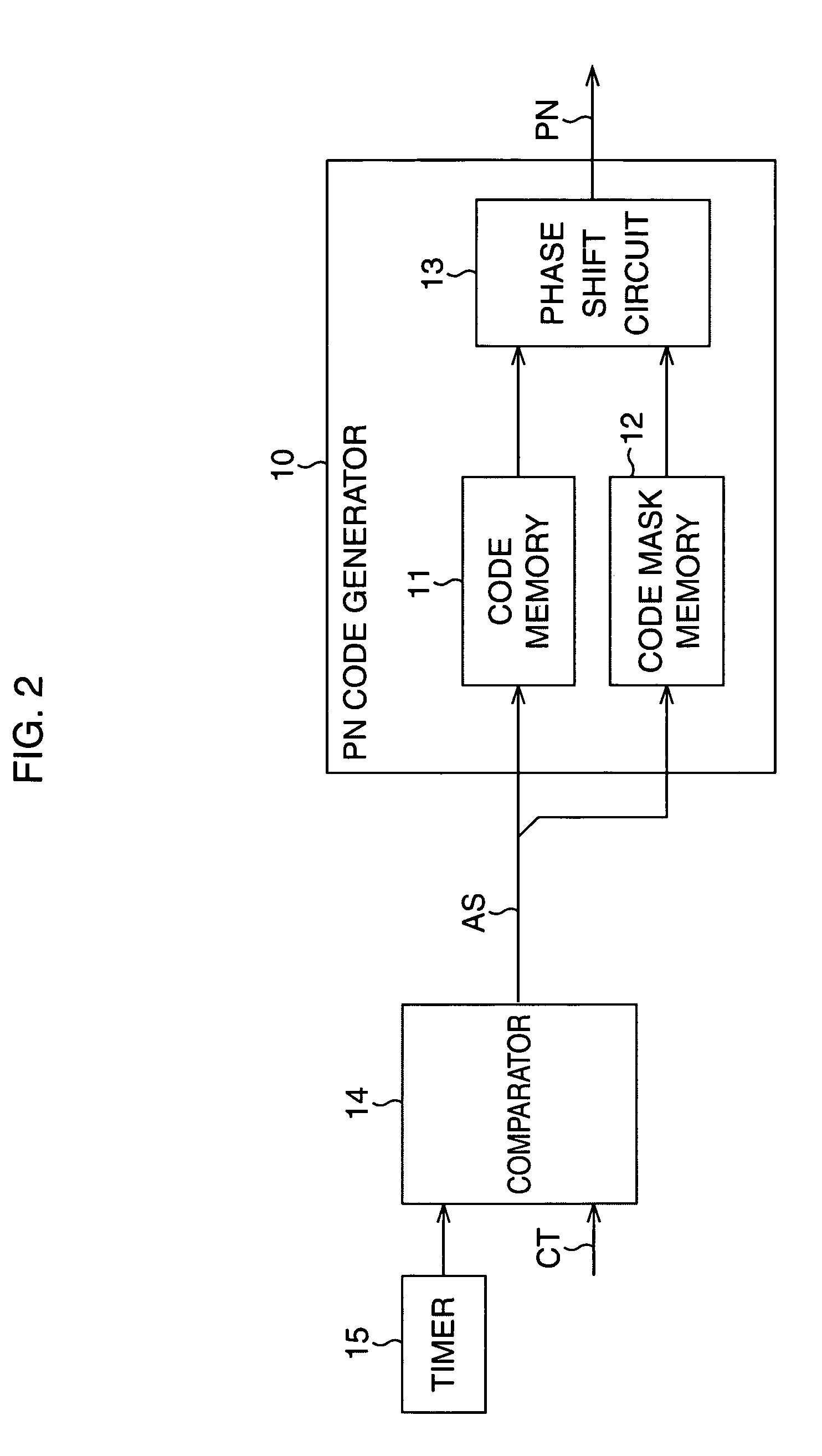
[0113]FIG. 8 is a view showing the second embodiment of the present invention, in which a schematic configuration of a PN code generator is shown. Incidentally, in FIG. 8, the same reference numerals and symbols in FIG. 1 to FIG. 6 are used to designate the same and corresponding elements as the PN code generator 10 according to the above-described first embodiment, and the detailed description thereof will not be given.

[0114]In FIG. 8, a PN code generator 70 has a code memory 71, a code mask memory 72, the phase shift circuit 13, and a distributor 74.

[0115]As s...

first modified example

[0123]Next, a first modified example of the above-stated second embodiment is described.

[0124]In the second embodiment described above, the code patterns to be stored in the code memory 71 are stored in the same address by every N bits. In this case, when the desired shift code pattern is laid over two addresses, it is necessary to perform read out operation twice. Consequently, in the present example, the code memory 71 is divided into two parts, and the divided addresses of the respective code memories are controlled individually.

[0125]Concretely explaining, for example, as shown in FIG. 9, the code memory 71 is divided into two code memories 71a and 71b, so that the code pattern stored in the same address by every N bits are divided into the code pattern from the beginning bit to the P (P≧N−1)th bit, and the code pattern from the (P+1)th bit to the 2 P-th bit. Next, the addresses of the divided respective code memories 71a, 71b are specified individually, and a required code is r...


PUM


Abstract

Shift code patterns at four continuous phases obtained by dividing 15 shift code patterns given to the respective flip-flops of a linear feedback shift register of degree 4 into four parts are stored in a code memory (11). Besides, mask code patterns to shift a phase of a PN code (PN) to be generated by every four phases, are stored in a code mask memory (12). Next, a logical operation is performed at a phase shift circuit (13) by using the shift code pattern outputted from the code memory (11) and the mask code pattern outputted from the code mask memory (12), to generate a PN code (PN) having a code length of 15 from a random phase.

Description

CROSS-REFERENCE TO RELATED APPLICATIONS[0001]This application is based upon and claims priority of International Patent Application No. PCT / JP2002 / 10576, filed on Oct. 11, 2002, the contents being incorporated herein by reference.TECHNICAL FIELD[0002]The present invention relates to a PN code generator, a GOLD code generator, a PN code despreader, a method for generating a PN code, a method for generating a GOLD code, a method for despreading a PN code, and a computer program, and in particular, it is suitable to be used for generating a code used in a CDMA (Code Division Multiple Access) method communication.BACKGROUND ART[0003]In a radio communication using a CDMA method, both a transmitting end and a receiving end use a same spread code to process a signal. Consequently, it becomes possible to transmit signals of plural channels by using a same frequency band at the same time at the transmitting end, and also, it becomes possible to extract only signals of intended channel from a...

Claims


Application Information

Patent Timeline
Patent Type & Authority Patents(United States)
IPC IPC(8): H04B1/00G06F7/58H03K3/84H04B1/707H04J11/00H04J13/10
CPCH04J13/10H03K3/84H04J13/0029H04J13/0022
Inventor SUNAGA, SUMIMASATANIGUCHI, SHOJIKANASUGI, MASAMIKUROIWA, KOICHI
Owner SOCIONEXT INC
Why Eureka
Try Eureka