Control apparatus for fuel cell vehicle and control method for fuel cell vehicle

a fuel cell and control apparatus technology, applied in hybrid vehicles, electric propulsion mountings, electrochemical generators, etc., can solve problems such as difficulty in executing traction control with suitable timing, risk of electrical power exceeding a specified upper limit, and lengthening the grip of the drive wheels. , to achieve the effect of adequate accuracy, long response delay and appropriate increase of grip for

Inactive Publication Date: 2008-08-19
HONDA MOTOR CO LTD
View PDF8 Cites 5 Cited by
  • Summary
  • Abstract
  • Description
  • Claims
  • Application Information

AI Technical Summary

Benefits of technology

[0054]As explained above, according to the control apparatus for the fuel cell vehicle of the present invention, execution of control of the power consumption of the motor, which has a relatively short response delay, can be promptly stated independently of control of the supply state of reactant gases, which have a relatively long response delay, and the motor output can be directly controlled with adequate accuracy, so the grip force can be appropriately increased immediately even, for example, when slippage of the wheels has occurred.
[0055]In addition, according to the control apparatus for the fuel cell vehicle of the present invention, because the supply state of the react gases is controlled in accordance with the power consumption of the motor, the generated power of the fuel cell can be prevented from becoming excessive or increasing unnecessarily.
[0056]In addition, according to the control apparatus for the fuel cell vehicle of the present invention, the generated power of the fuel cell can be appropriately set in accordance with the operating state of the motor.
[0057]In addition, according to the control apparatus for the fuel cell vehicle of the present invention, the power consumption of the motor for controlling the supply state of the reactant gases can be set in accordance with whether or not traction control is being executed, and the generated power of the fuel cell can be suitably set in accordance with whether or not traction control is being executed.
[0058]In addition, according to the control apparatus for the fuel cell vehicle of the present invention, even in the case that the power consumption of the motor increases with a relatively short response delay in accordance with the driving force of the motor, a shortage in the supply of reactant gases to the fuel cell due to the power consumption of the motor exceeding the electrical output of the fuel cell can be prevented during the period until the electrical output of the fuel cell is increased by controlling the supply state of the reactant gases having a relatively longer response delay. Thereby, hastening of degradation of the fuel cell due to an excessive electrical current command being placed on the fuel cell leading to a shortage in the supply of reactant gases can be prevented.
[0059]In addition, according to the control apparatus for the fuel cell vehicle of the present invention, when for example returning from the state of executing driving force control by the traction control unit, that is, even when shifting from the state of the driving force of the motor changing in accordance with the torque required for traction in traction control to the state of the driving force of the motor changing in accordance with the driver-requested torque corresponding to the accelerator opening degree, a shortage in the generated power of the fuel cell, that is, a shortage in the supply of reactant gases, is prevented, and so hastening of degradation of the fuel cell can be prevented.

Problems solved by technology

For this reason, from the moment slippage of the drive wheels is detected, the time required for output of the vehicle traction motor to be actually restricted for the grip of the drive wheels to increase is lengthened, leading to difficulty in executing traction control with suitable timing.
Moreover, when the output of the vehicle traction motor rapidly increases, such as when the tires slip on a road surface with a relatively low frictional resistance due to freezing or the like, there is the risk of electrical power exceeding a specified upper limit power from the fuel cell and an electrical storage apparatus during the time from the detection of the output surge to restricting the electrical power supplied to the traction motor by restricting the supply state of fuel to the fuel cell.
This gives rise to the risk of being unable to suitably protect the fuel cell and the electrical storage apparatus.

Method used


Image

  • Control apparatus for fuel cell vehicle and control method for fuel cell vehicle
  • Control apparatus for fuel cell vehicle and control method for fuel cell vehicle
  • Control apparatus for fuel cell vehicle and control method for fuel cell vehicle

Examples


first embodiment

[0091]A control apparatus for a fuel cell vehicle and a control method for a fuel cell vehicle according to the present invention shall be described below with reference to the attached drawings.

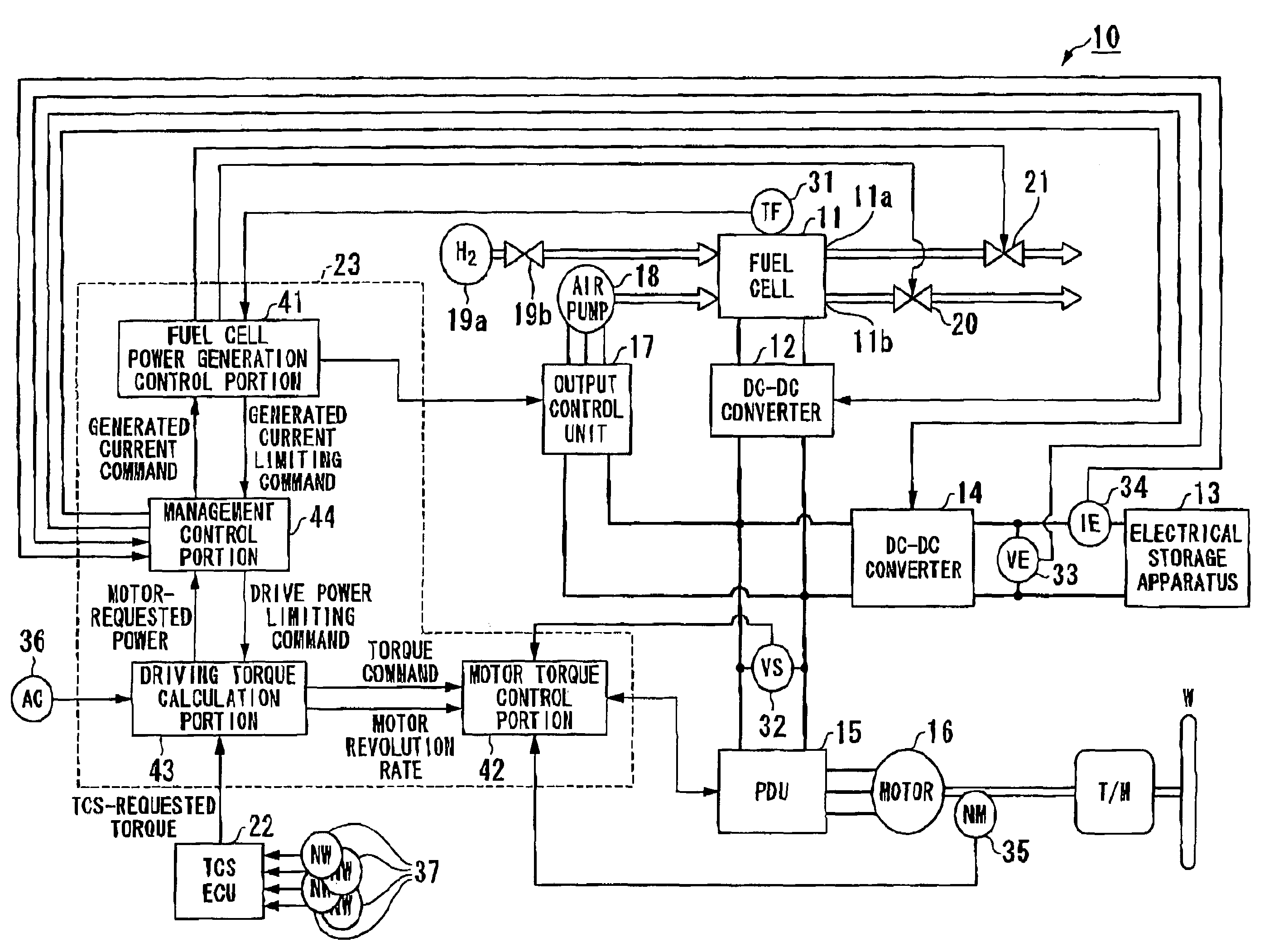
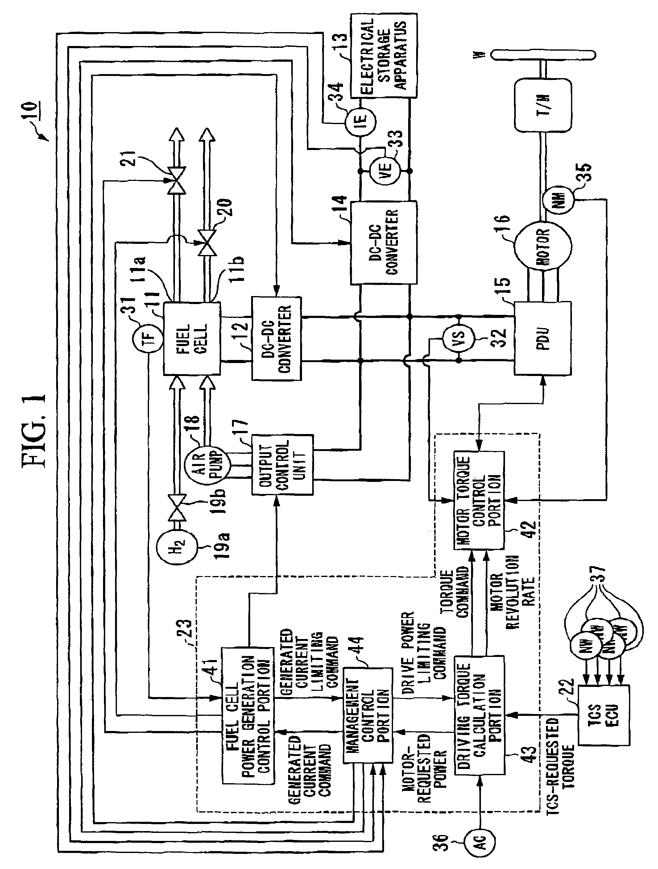
[0092]A control apparatus 10 for the fuel cell vehicle of the present embodiment is, as shown in FIG. 1, constituted by a fuel cell 11, a first DC-DC converter 12, an electrical storage apparatus 13, a second DC-DC converter 14, a power drive unit (PDU) 15, a motor 16, an output control unit 17, an air pump 18, a hydrogen tank 19 and a hydrogen supply value 19b, a back pressure valve 20, a purge valve 21, a traction control system electronic control unit (TCSECU) 22, a control apparatus 23; a fuel cell temperate sensor 31; a system voltage sensor 32, a terminal voltage sensor 33, a current sensor 34, a motor revolution rate sensor 35, an accelerator opening degree sensor 36, and wheel speed sensors 37.

[0093]The control apparatus 23 is constituted by, for example, a fuel cell power generation...

second embodiment

[0158]A control apparatus for a fuel cell vehicle and a control method for a fuel cell vehicle according to the present invention shall be described below with reference to the attached drawings.

[0159]In the control apparatus 10 for the fuel cell vehicle and the control method for the fuel cell vehicle according to the first embodiment of the present invention described above, during execution of traction control the supply state of the reactant gases is controlled in accordance with the power consumption of the motor 16 (for example, the motor-requested power PM). However, in the control apparatus for the fuel cell vehicle and the control method for the fuel cell vehicle according to the second embodiment of the present invention described below, during execution of traction control the supply state of the reactant gases is controlled irrespective of the drive power of the motor 16.

[0160]In the control apparatus 10 for the fuel cell vehicle and the control method for the fuel cell ...


PUM

PropertyMeasurementUnit
poweraaaaaaaaaa
power consumptionaaaaaaaaaa
torqueaaaaaaaaaa

Abstract

A control apparatus for a fuel cell vehicle includes: a motor for driving the fuel cell vehicle; a motor control unit controlling driving and regenerative operations of the motor; a traction control unit suppressing slippage of drive wheels by controlling a driving force acting between tires and a road surface; a fuel cell generating electricity through electrochemical reaction by being supplied with reactant gases by a reactant gas supply unit and supplies electrical power to the motor; an electrical storage apparatus charged by power generated by the fuel cell and power regenerated by the motor; an output control unit controlling the output of the fuel cell; and a control unit controlling power consumption of the motor in advance of a change in a supply state of the reactant gases to the fuel cell due to execution of driving force control by the traction control unit.

Description

BACKGROUND OF THE INVENTION[0001]1. Field of the Invention[0002]The present invention relates to a control apparatus for a fuel cell vehicle and a control method for a fuel cell vehicle.[0003]Priority is claimed on Japanese Patent Application No. 2005-196186, filed Jul. 5, 2005, the content of which is incorporated herein by reference.[0004]2. Description of Related Art[0005]There is conventionally known a control apparatus that performs traction control to suppress slippage of drive wheels due to excessive driving force being applied from the tires to the road surface in a vehicle equipped with a fuel cell and an electrical storage apparatus as a power supply for the vehicle traction motor (refer, for example, to Japanese Unexamined Patent Application, First Publication No. 2001-204107). This control apparatus restricts the electrical power supplied from the fuel cell to the vehicle traction motor by restricting the fuel supplied to the fuel cell, whereby the output of the vehicle ...

Claims


Application Information

Patent Timeline
Patent Type & Authority Patents(United States)
IPC IPC(8): B60K1/00B60L11/18H01M8/00H01M8/04H01M8/10
CPCB60K28/16Y10S903/908
Inventor UENODAI, ASAOSHIRASAKA, TAKUYAIKEDA, TOHRUYANAGIDA, HISANORI
Owner HONDA MOTOR CO LTD
Why Eureka
Try Eureka