
Receiver including synch pulse detection and associated method

a technology of asynchronous receivers and detection methods, applied in the field of communication systems, can solve problems such as difficult noise-only thresholds, signal-to-noise losses, and affect the performance of match filters, and achieve the effect of increasing the probability of asynchronous receiver detection

Inactive Publication Date: 2008-08-19
HARRIS CORP
View PDF11 Cites 2 Cited by
  • Summary
  • Abstract
  • Description
  • Claims
  • Application Information

AI Technical Summary

Benefits of technology

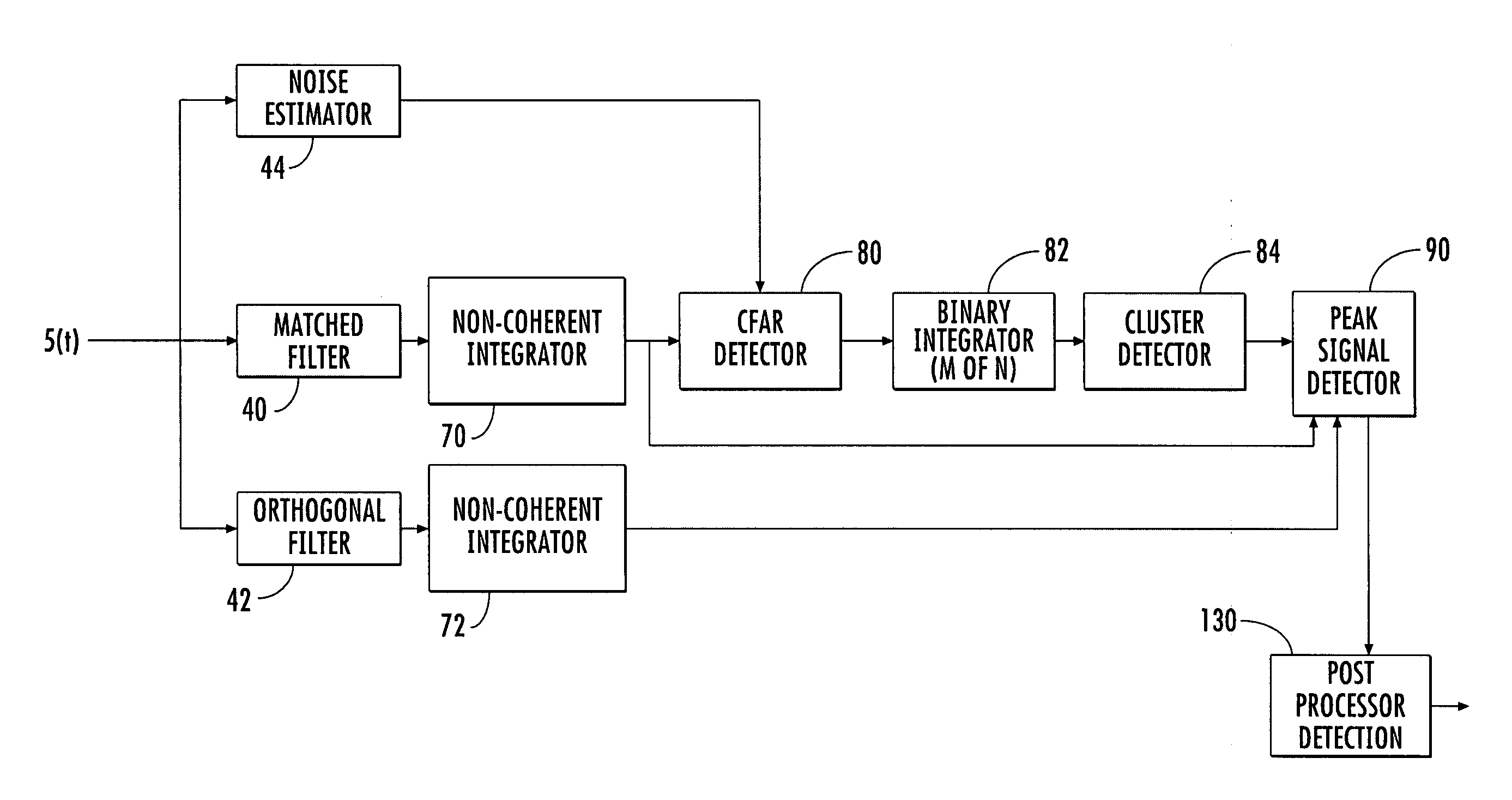
"The present invention provides a receiver that can detect synch pulses with a higher probability. The receiver comprises a matched filter and an orthogonal filter that generate output signals with peaks and valleys that correspond to the synch pulse. A detector then determines the synch pulse based on the difference between the matched filter and the orthogonal filter output signals. The receiver also includes non-coherent integrators and a constant false alarm rate detector to further improve the detection of synch pulses. The method for detecting synch pulses in a receiver involves generating output signals from a matched filter and an orthogonal filter, and detecting the synch pulse based on the difference between the output signals."

Problems solved by technology

Even though matched filters are straightforward to implement, there are several limitations.
These limitations include signal-to-noise losses due to the frequency uncertainty of the synch pulses, and setting a noise-only threshold can be difficult when balancing the probability-of-detection (pod) to the probability-of-false alarms (pfa).
Since the synch pulses are typically at power levels lower than power levels of the data pulses, jammer or high noise level interference can mask the synch pulses, which in turn affects performance of the match filters.
A limitation of CFAR detectors is also with respect to a masking of the synch pulses due to threshold levels typically being higher than necessary, thus resulting in a reduced probability-of-detection.
As with matched filters, the need for increased threshold levels for CFAR detectors is due to inaccuracies in non-homogenous environments affected by antenna gain / noise temperature (G / T) variations and jammers.
In addition, the signals containing the synch pulses may also fade in and out due to irregularities in the atmospheres.

Method used


Image

  • Receiver including synch pulse detection and associated method
  • Receiver including synch pulse detection and associated method
  • Receiver including synch pulse detection and associated method

Examples


Embodiment Construction

[0023]The present invention will now be described more fully hereinafter with reference to the accompanying drawings, in which preferred embodiments of the invention are shown. This invention may, however, be embodied in many different forms and should not be construed as limited to the embodiments set forth herein. Rather, these embodiments are provided so that this disclosure will be thorough and complete, and will fully convey the scope of the invention to those skilled in the art. Like numbers refer to like elements throughout.

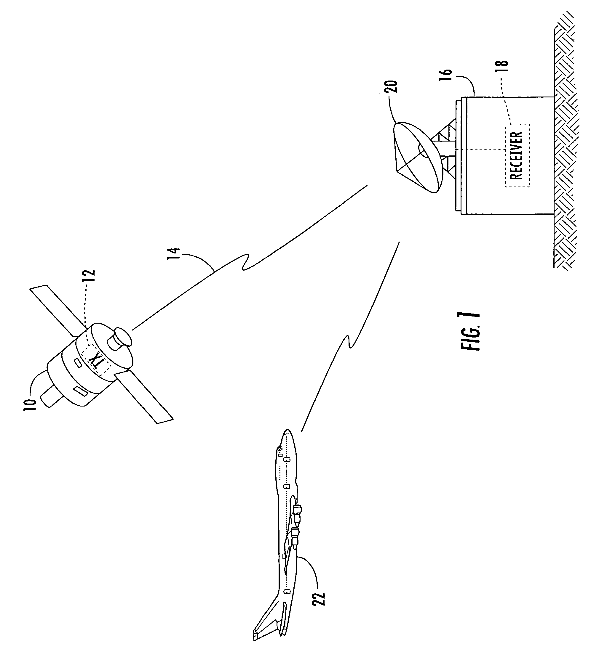
[0024]For purposes of discussing the present invention, a satellite 10 having a transmitter 12 transmits signals 14 to a ground station 16, as illustrated in FIG. 1. A receiver 18 in the ground station 16 receives the transmitted signals 14 via antenna 20. The transmitted signals 14 include data pulses and synch pulses, which may be time and frequency hopped to reduce the probability of being detected by an undesired receiver. Frequency hopping also reduce...


PUM


Abstract

A receiver includes a matched filter matched to a synch pulse and generates a matched filter output signal having peaks and valleys with one of the peaks corresponding to the synch pulse. An orthogonal filter is inversely matched to the synch pulse and generates an orthogonal filter output signal having peaks and valleys with one of the valleys corresponding to the synch pulse. A detector determines the synch pulse based upon a largest difference between the matched filter output signal and the orthogonal filter output signal.

Description

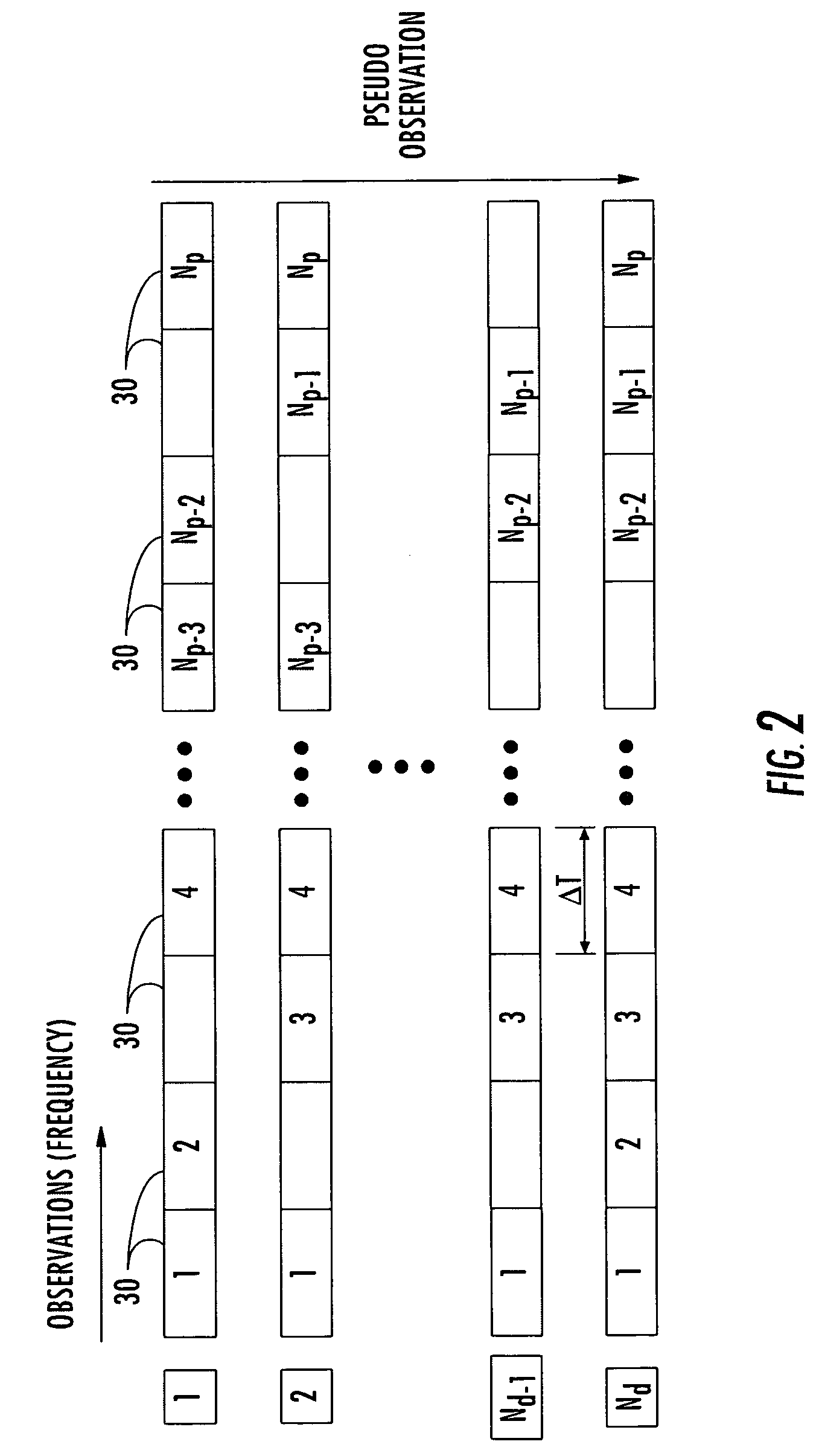
GOVERNMENT LICENSE RIGHTS[0001]This invention was made with Government support under contract No. AEHF-NMT N00039-04-C-0011 awarded by the United States Navy. The Government has certain rights in this invention.FIELD OF THE INVENTION[0002]The present invention relates to the field of communication systems, and more particularly, to a receiver using various filters for synch pulse detection and related methods.BACKGROUND OF THE INVENTION[0003]Frequency hopping is a commonly used technique for providing secure communication systems. A frequency hopping communication system is a type of spread spectrum system in which a wideband signal is generated by hopping from one frequency to another over a large number of frequency choices. In systems using very fast frequency hopping, the signal is transmitted at each frequency for a very short period, such as 20 ms, for example.[0004]Transmission of frequency hopped signals include synch pulses and data pulses. The synch pulses allow a receiver...

Claims


Application Information

Patent Timeline
Patent Type & Authority Patents(United States)
IPC IPC(8): H04L27/06H04B1/713H04L7/06
CPCH04L7/027H04L7/0054
Inventor BEADLE, EDWARD R.DISHMAN, JOHN F.
Owner HARRIS CORP
Learn More