Diaphragm valve for the vacuum exhaustion system

a vacuum exhaustion system and diaphragm valve technology, which is applied in the direction of diaphragm valves, positive displacement liquid engines, engine diaphragms, etc., can solve the problems of large facilities, inability to raise the pressure on the discharge outlet side, and inability to manufacture. easy, the effect of preventing damage and abrasion of the valve seat and the diaphragm

Active Publication Date: 2008-08-26
OHMI TADAHIRO +1
View PDF22 Cites 32 Cited by
  • Summary
  • Abstract
  • Description
  • Claims
  • Application Information

AI Technical Summary

Benefits of technology

[0018]The present invention has been created to solve the above mentioned problems. An object of the present invention is to provide a diaphragm valve for the vacuum exhaustion system which can prevent the corrosions caused by the accumulation and adherence of the substances produced by the thermal decomposition of the gas, the cloggings caused by the substances as produced, and the valve seat leakages. It is also an object of the present invention to provide a valve for the vacuum exhaustion system which can make the facilities for the vacuum exhaustion system small-sized and, as a result, lower the costs, and further reduce the diameter of the pipings for the vacuum exhaustion system for shortening the vacuum exhaustion time.DISCLOSURE OF THE INVENTION
[0025]The parts where the synthetic resin film is coated are desirably the surfaces of the flow-in passage, the flow-out passage and the valve seat, and further the lower side of the diaphragm all of which the fluid is allowed to contact. In this manner, the coating is limited to the parts where the coating is necessary, thus further making it possible to reduce the costs.

Problems solved by technology

However, in reality, the vacuum exhaustion pump having a high compression ratio is not easily available.
However, as stated above, with the conventional pump having a comparatively small compression ratio (approximately 10), it is not possible to raise the pressure on the discharge outlet side.
As a result, with the conventional vacuum exhaustion system, there is a problem that since the piping system having a large diameter is required, the facilities are made large-sized.
Further, there is another problem that since a larger inside diameter of the vacuum pipe system means a larger volume inside the pipe, it takes a longer time for the vacuum exhaustion Furthermore, to effect the exhaustion operation efficiently in a short time by the vacuum exhaustion system, an expensive vacuum pump having a large compression ratio and a high velocity of exhaustion is needed.
However, if the pressure is raised as mentioned above, moisture or gas condenses in the vacuum exhaustion piping system and adheres to the inside of the pipings.
Further, even if the condensation and adherence of water, moisture or gas caused by the pressure rise do not occur, the decomposition of the gas remaining inside the pipings happens when the vacuum pump is out of operation.
As a result, substances produced by the gas decomposition accumulates inside the pipings and piping parts of the valve, causing the corrosion of the parts, the clogging of the valves by the substances as produced and the valve seat leakages.
That is, when the temperature is raised by the heating, the saturated vapor pressure rises, making it difficult for the condensation and adherence of water, moisture or gas to occur with the result that the risk of the corrosion and cloggings is reduced.
However, the gas is decomposed (or dissociated) when the temperature rises.
Here occurs another problem that the substances produced by the decomposition of the gas adhere to the inside of the pipings and, as a result, cause the corrosion and the like.

Method used


Image

  • Diaphragm valve for the vacuum exhaustion system
  • Diaphragm valve for the vacuum exhaustion system
  • Diaphragm valve for the vacuum exhaustion system

Examples


Embodiment Construction

[0031]The embodiment in accordance with the present invention is described hereunder with reference to the drawings.

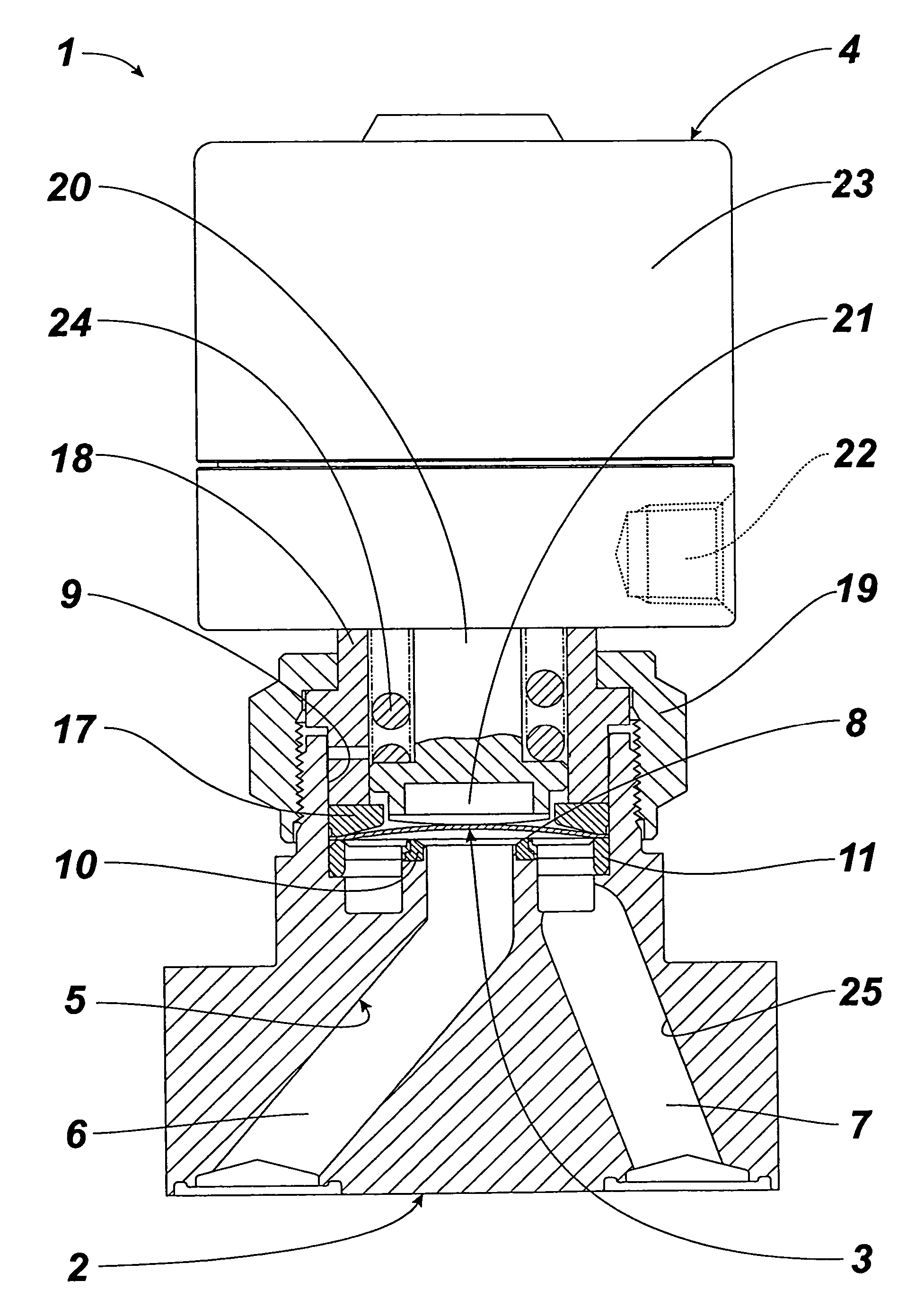
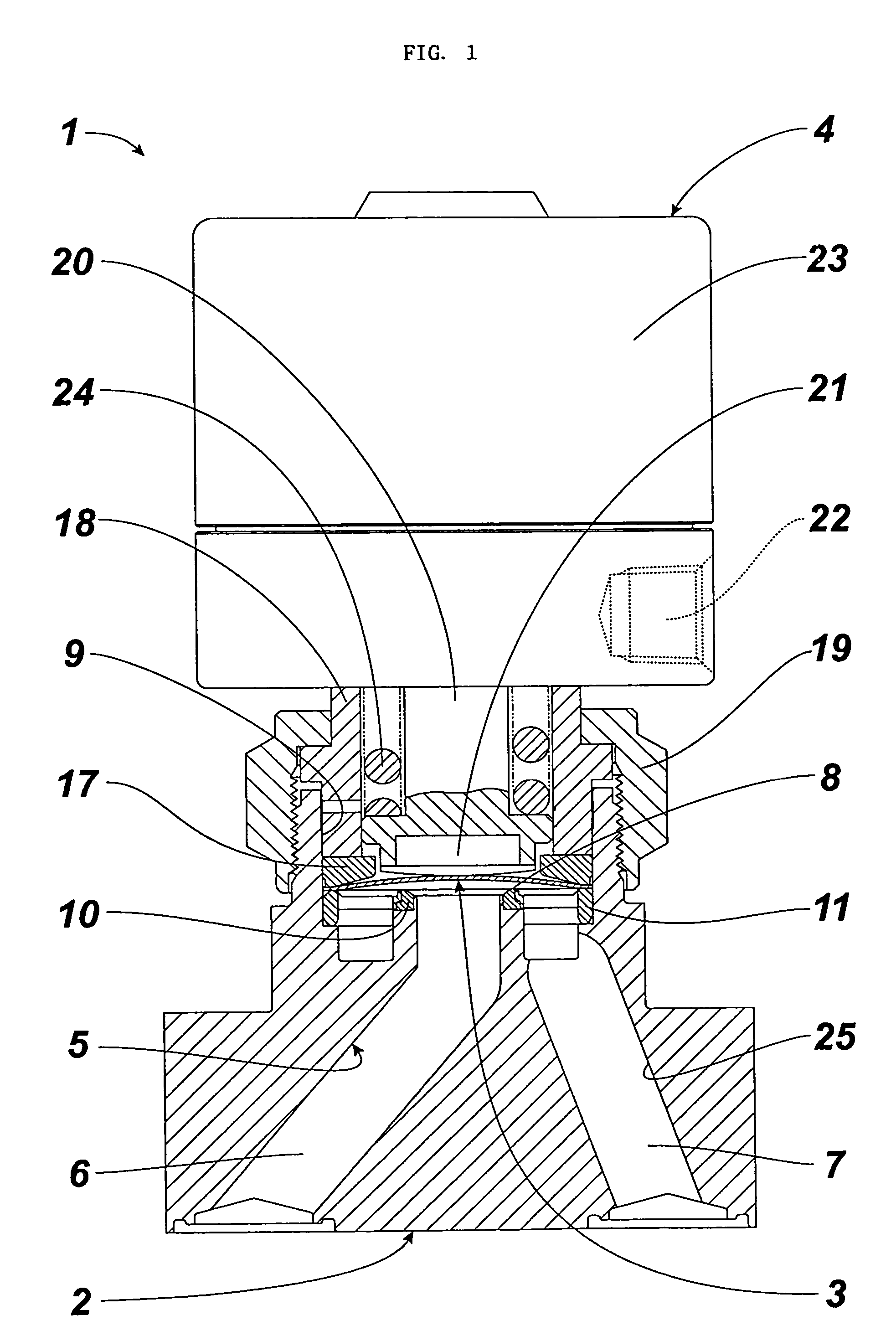
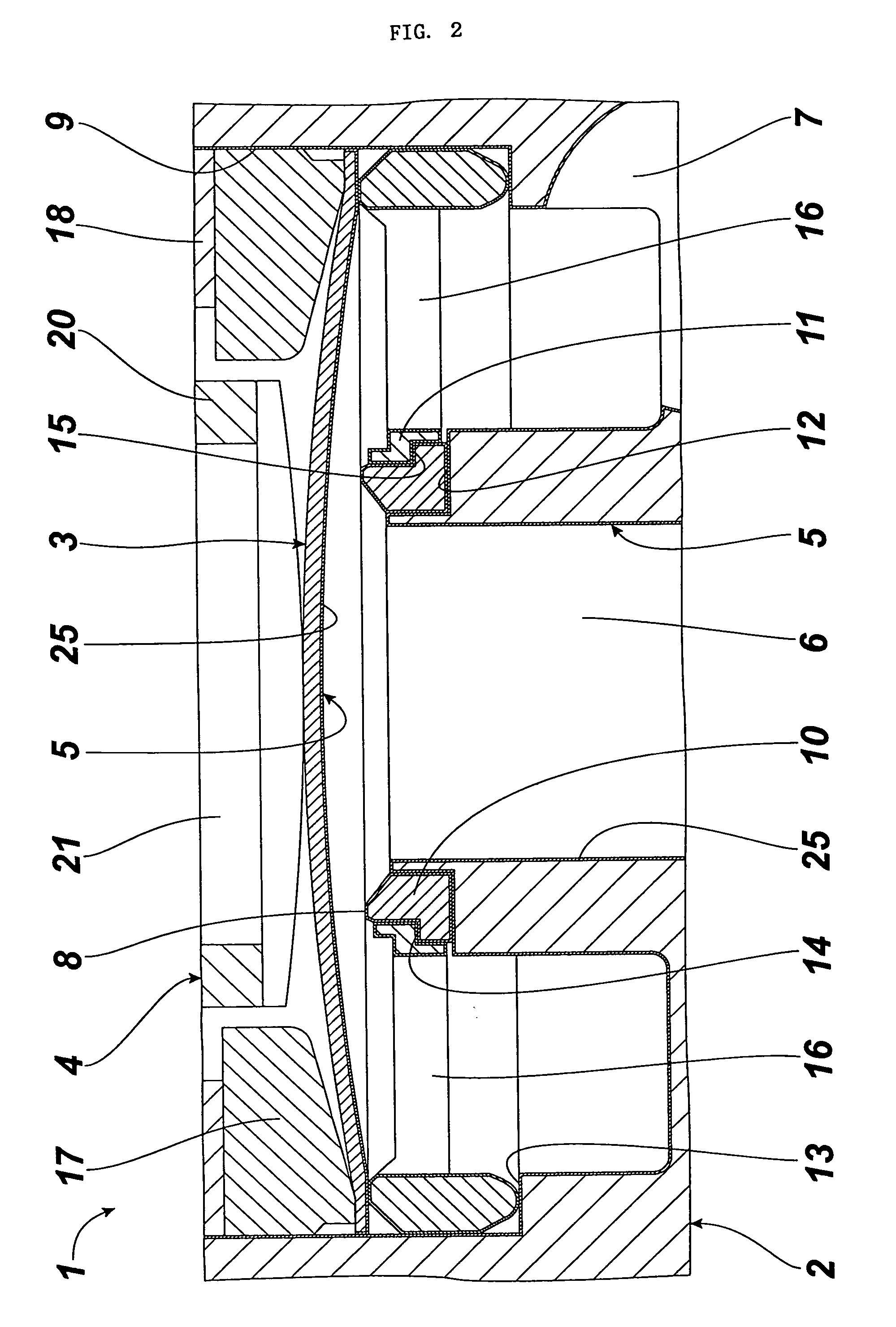
[0032]FIG. 1 is a longitudinal sectional view of a diaphragm valve according to the present invention. FIG. 2 is a longitudinal sectional view of an enlarged essential part of FIG. 1. FIG. 3 is a graph to show the relationship between the decomposition and temperatures of various gases where Spron is coated with Teflon.

[0033]A major part of the diaphragm valve 1 comprises a body 2, a diaphragm 3, a driving means 4 and a synthetic resin film 5. The diaphragm valve 1 is a normally open, direct touch type valve which is employed between a process chamber and a primary pump, or between the primary pump and a secondary pump in the vacuum exhaustion system.

[0034]The body 2 includes a flow-in passage 6, a flow-out passage 7 and a valve seat 8 formed between the two passages and made of stainless steel (i.e., SUS316L and the like) in this case. That is, the body 2 comprises th...


PUM


Abstract

A diaphragm valve 1 is provided with a body 2 having a flow-in passage 6, a flow-out passage 7, and a valve seat 8 formed between the passages; a diaphragm 3 installed in the body 2 and permitted to rest on and move away from the valve seat 8; and a driving means 4 installed on the body 2 to allow the diaphragm 3 to rest on and move away from the valve seat 8, wherein synthetic resin films 5 of predetermined thickness are coated on fluid-contacting parts 25 of the afore-mentioned body 2 and diaphragm 3. A diaphragm valve in accordance with the present invention prevents corrosion of the valve members caused by accumulation and adherence of substances produced by thermal decomposition, and prevents clogging caused by substances produced, and prevents seat leakage when applied in the vacuum exhaust system of a semiconductor manufacturing facility.

Description

[0001]This is a National Phase Application in the United States of International Patent Application No. PCT / JP2004 / 001346 filed Feb. 9, 2004, which claims priority on Japanese Patent Application No. 2003-039541, filed Feb. 19, 2003. The entire disclosures of the above patent applications are hereby incorporated by reference.FIELD OF THE INVENTION [0002]The present invention is applicable to, for example, the semiconductor manufacturing equipment. More particularly, the present invention is concerned with improvements in a diaphragm valve to be used in the system for the vacuum exhaustion from a process chamber employed in the semiconductor manufacturing.BACKGROUND OF THE INVENTION [0003]Generally, a gas having high chemical reactivity is supplied to the process chamber used in the semiconductor manufacturing facilities and the like. Accordingly, the vacuum exhaustion system for the process chamber is required to exhaust high reactivity gases in safety and with a high degree of effic...

Claims


Application Information

Patent Timeline
Patent Type & Authority Patents(United States)
IPC IPC(8): F16K31/122F16K7/17F04B45/04F16K7/16F16K51/02
CPCF16K51/02F16K7/16F16K25/005F16K25/04
Inventor OHMI, TADAHIROIKEDA, NOBUKAZUYAMAJI, MICHIOKITANO, MASAFUMIMORIMOTO, AKIHIRO
Owner OHMI TADAHIRO
Why Eureka
Try Eureka