Submerged gas evaporators and reactors

a gas evaporator and submerged technology, applied in the field of devices, can solve the problems of high degree of mixing between the gas and the process fluid, and any suspended particles within the process fluid, and achieve the effects of significantly reducing the degree of turbulence, clogging and fouling associated with other submerged gas processors, and eliminating the whole or a large proportion of them

Active Publication Date: 2008-08-26
SHAW INTPROP HLDG INC
View PDF40 Cites 77 Cited by
  • Summary
  • Abstract
  • Description
  • Claims
  • Application Information

AI Technical Summary

Benefits of technology

[0016]During operation, gas introduced through the tube mixes with the process fluid in a first confined volume formed by the weir, and the fluid mixture of gas and liquid flows at high volume with a high degree of turbulence along the circulation path defined around the weir, thereby causing a high degree of mixing between the gas and the process fluid and any suspended particles within the process fluid. Shear forces within this two-phase or three-phase turbulent flow that result from the high density liquid phase overrunning the low density gas phase create extensive interfacial surface area between the gas and the process fluid that favors minimum residence time for mass and heat transfer between the liquid and gas phases to come to equilibrium compared to conventional gas dispersion techniques. Still further, vigorous mixing created by the turbulent flow hinders the formation of large crystals of precipitates within the process fluid and, because the system does not use small holes or other ports to introduce the gas into the process fluid, clogging and fouling associated with other submerged gas processors are significantly reduced or entirely eliminated. Still further, the predominantly horizontal flow direction of the liquid and gas mixture over the top of the weir and along the surface of the process fluid within the processing vessel enables the gas phase to disengage from the process fluid with minimal entrainment of liquid due to the significantly greater momentum of the much higher density liquid that is directed primarily horizontally compared to the low density gas with a relatively weak but constant vertical momentum component due to buoyancy.

Problems solved by technology

During operation, gas introduced through the tube mixes with the process fluid in a first confined volume formed by the weir, and the fluid mixture of gas and liquid flows at high volume with a high degree of turbulence along the circulation path defined around the weir, thereby causing a high degree of mixing between the gas and the process fluid and any suspended particles within the process fluid.

Method used


Image

  • Submerged gas evaporators and reactors
  • Submerged gas evaporators and reactors
  • Submerged gas evaporators and reactors

Examples


Embodiment Construction

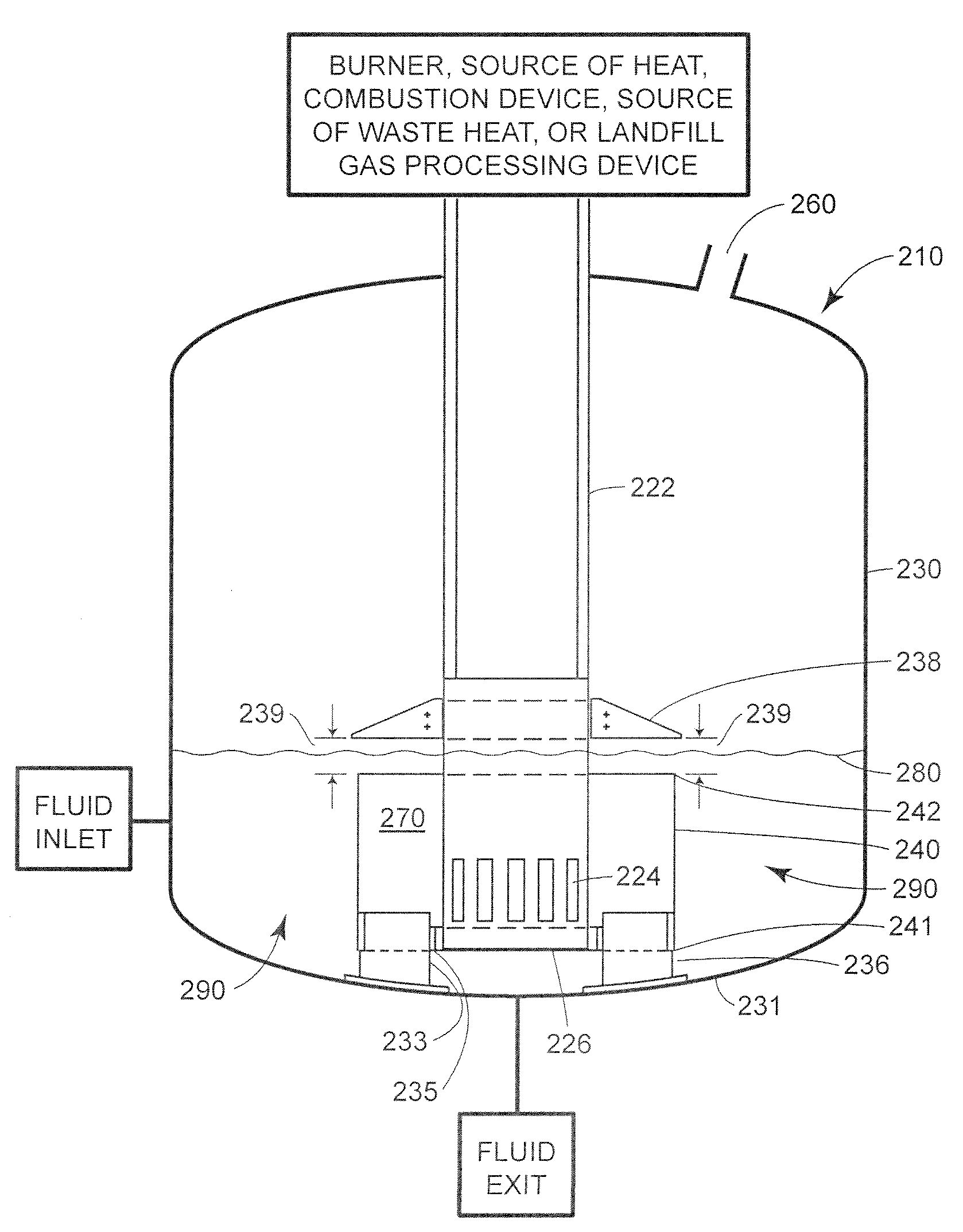
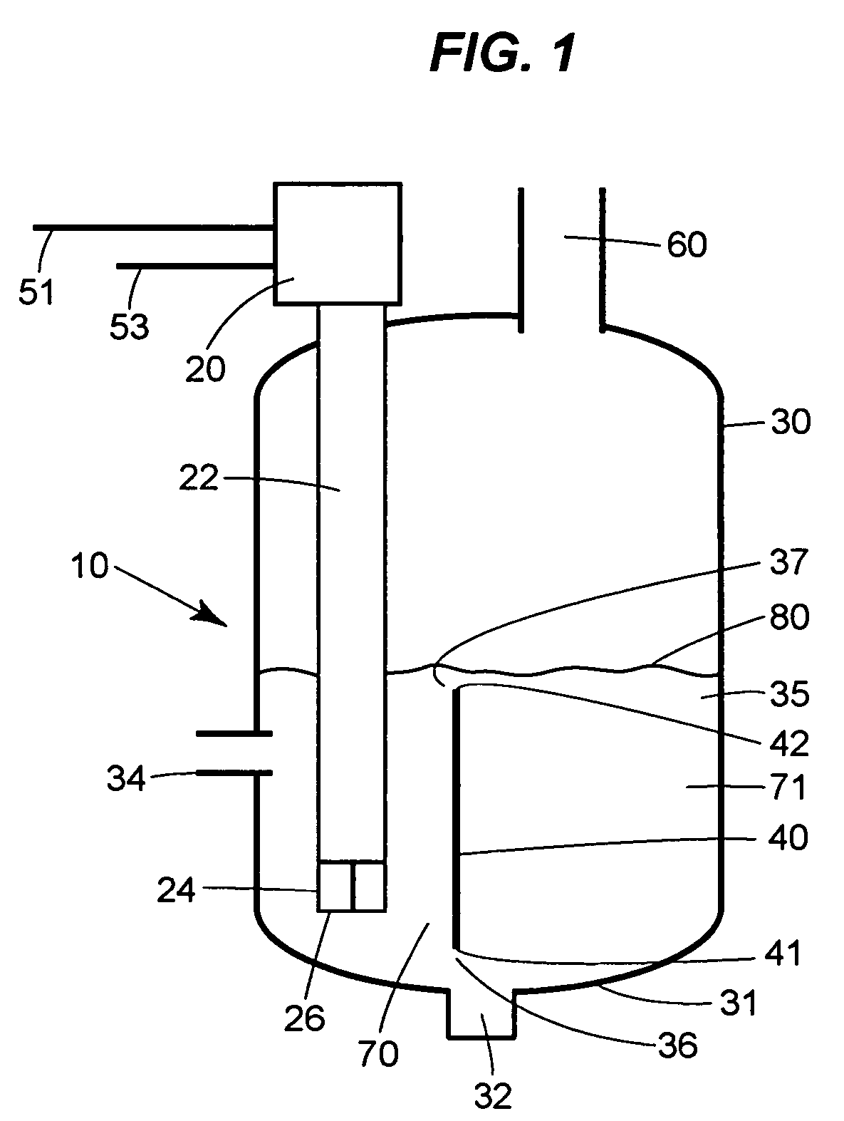
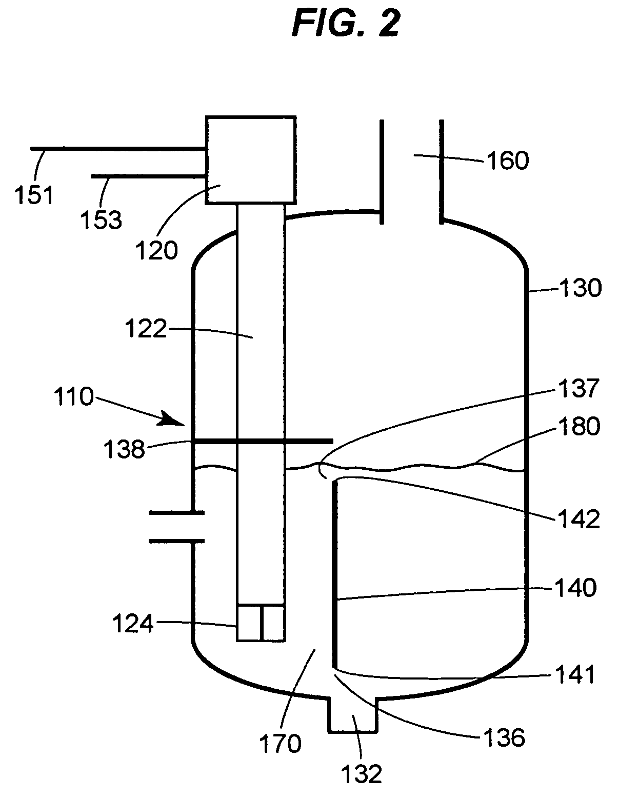
[0024]Referring to FIG. 1, a submerged gas processor 10, in the form of a submerged combustion gas evaporator, includes a burner 20 and a hot gas supply tube or gas inlet tube 22 having sparge or gas exit ports 24 at or near an end 26 thereof. The gas inlet tube 22 is disposed within an evaporator vessel 30 having a bottom wall 31 and a process fluid outlet port 32. A process fluid inlet port 34 is disposed in one side of the vessel 30 and enables a process fluid 35 (and other liquids) to be provided into the interior of the vessel 30. Additionally, a weir 40, which is illustrated in FIG. 1 as a flat or solid plate member having a first or lower end 41 and a second or upper end 42, is disposed within the vessel 30 adjacent the gas inlet tube 22. The weir 40 defines and separates two volumes 70 and 71 within the vessel 30. As illustrated in FIG. 1, a gas exit port 60 disposed in the top of the vessel 30 enables gas to exit from the interior of the vessel 30.

[0025]In the submerged com...


PUM

PropertyMeasurementUnit
distanceaaaaaaaaaa
diametersaaaaaaaaaa
diametersaaaaaaaaaa

Abstract

A submerged gas processor in the form of an evaporator or a submerged gas reactor includes a vessel, a gas delivery tube partially disposed within the vessel to deliver a gas into the vessel and a process fluid inlet that provides a process fluid to the vessel at a rate sufficient to maintain a controlled constant level of fluid within the vessel. A weir is disposed within the vessel adjacent the gas delivery tube to form a first fluid circulation path between a first weir end and a wall of the vessel and a second fluid circulation path between a second weir end and an upper end of the vessel. During operation, gas introduced through the tube mixes with the process fluid and the combined gas and fluid flow at a high rate with a high degree of turbulence along the first and second circulation paths defined around the weir, thereby promoting vigorous mixing and intimate contact between the gas and the process fluid. This turbulent flow develops a significant amount of interfacial surface area between the gas and the process fluid resulting in a reduction of the required residence time of the gas within the process fluid to; achieve thermal equilibrium and / or to drive chemical reactions to completion, all of which leads to a more efficient and complete evaporation, chemical reaction, or combined evaporation and chemical reaction process.

Description

FIELD OF THE DISCLOSURE[0001]The present disclosure relates generally to devices that mix gases and liquids, and more specifically, to submerged gas processors including submerged gas evaporators and submerged gas reactors.BACKGROUND[0002]Submerged gas evaporators, submerged gas reactors and combination submerged gas evaporator / reactor systems in which gas is dispersed within the liquid phase, referred to generally herein as submerged gas processors, are well known types of devices used in many industries to perform evaporation and chemical reaction processes with respect to various constituents. U.S. Pat. No. 5,342,482 discloses a common type of submerged combustion gas evaporator, in which combustion gas is generated and delivered though an inlet pipe to a dispersal unit submerged within the liquid to be evaporated. The dispersal unit includes a number of spaced-apart gas delivery pipes extending radially outward from the inlet pipe, each of the gas delivery pipes having small hol...

Claims


Application Information

Patent Timeline
Patent Type & Authority Patents(United States)
IPC IPC(8): B01F3/04
CPCB01D1/14B01F3/04248B01F15/00883B01J19/2405B01J2219/00777B01J2219/00135B01J2219/00166B01J2219/00768B01F23/23121B01F35/531
Inventor DUESEL, JR., BERNARD F.GIBBONS, JOHN P.RUTSCH, MICHAEL J.
Owner SHAW INTPROP HLDG INC
Why Eureka
Try Eureka