Continuous observation apparatus and method of magnetic flux distribution

a continuous observation and magnetic flux technology, applied in the direction of instruments, superconductivity measurement, material magnetic variables, etc., can solve the problems of difficult detection of small size defects, deterioration of superconductivity performance, and failure to carry out efficient continuous and speedy measurement of long samples, so as to improve measurement efficiency and measurement accuracy. , the effect of efficient measuremen

Inactive Publication Date: 2008-08-26
FUJIKURA LTD +1
View PDF4 Cites 4 Cited by
  • Summary
  • Abstract
  • Description
  • Claims
  • Application Information

AI Technical Summary

Benefits of technology

[0018]Further, since the cooling procedure is used to give temperature control to a sample at the cooling / retaining portion, it is possible to efficiently control temperatures at an observation area and also provide a more stable temperature control at a shorter time than a case where a whole sample is controlled for temperature.
[0043]According to the continuous observation method of magnetic flux distribution of the present invention, an effect is obtained such that a sample transferred to the observation position is kept lower in temperature than that at the observation position and less likely to be influenced by the magnetic flux penetration before arrival at the observation position, thereby making it possible to increase measurement accuracy, and also a reduced influence of heat transmitted externally via a long sample leads to a stable temperature control of the sample at the observation position and increases measurement efficiency.

Problems solved by technology

Where there are defects such as micro cracks or existence of secondary phases and etc. inside a superconducting material, it is conventionally known that a weak coupling region will allow an external magnetic flux to penetrate into the superconducting material, resulting in deteriorated performance of superconductivity.
However, the above-described conventional magnetic flux observing apparatus has the following problems.
The technique has another problem in that because the indicator film of magneto-optical imaging with perpendicular to film surface has magnetic domain patterns, a complicated image processing for calculating the width of a magnetic domain is required in effecting conversion to the magnetic flux density distribution and a longer time is required in making one measurement resulting in failure of carrying out an efficient continuous and speedy measurement of long samples.
Further, another problem is that the measurement resolution will depend on the spacing width of a magnetic domain due to the use of a perpendicular magnetic film.
Because the spacing width of magnetic domain increases in higher magnetic field, it is difficult to detect a small size defect, that is to say weak coupling regions, which are smaller than several millimeters.
Further, if the same technique described in the above paper reported by Furtner et al. is used to observe magneto-optical images, the apparatus is placed inside a liquid nitrogen vessel to observe light through the liquid nitrogen, thereby making it difficult to obtain clear images and make a highly accurate observation, and therein exists another problem to be solved.
As for the magnetic tapes, for example magnetic recording tapes such as a main medium in a flight recorder, there is no method to detect the two dimensional information from the magnetic tapes with non-destructive way.

Method used


Image

  • Continuous observation apparatus and method of magnetic flux distribution
  • Continuous observation apparatus and method of magnetic flux distribution
  • Continuous observation apparatus and method of magnetic flux distribution

Examples


Embodiment Construction

[0053]Hereinafter, an explanation will be made of an embodiment of the present invention by referring to the attached drawings.

[0054]Then, an explanation will be made of continuous observation apparatus of magnetic flux distribution to the embodiment of the present invention.

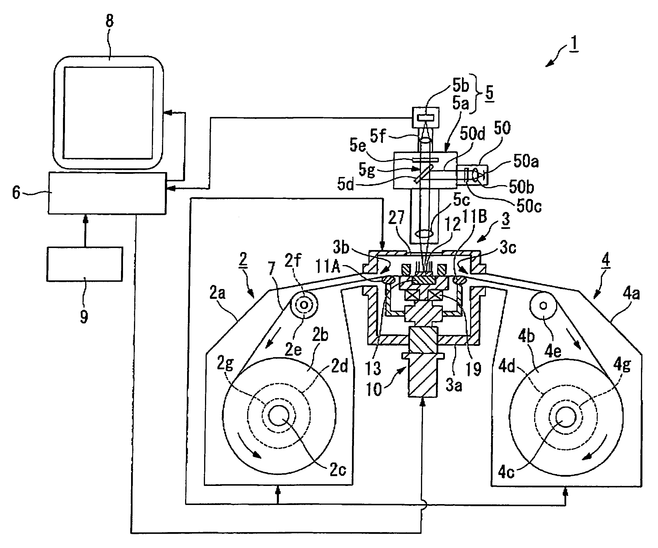
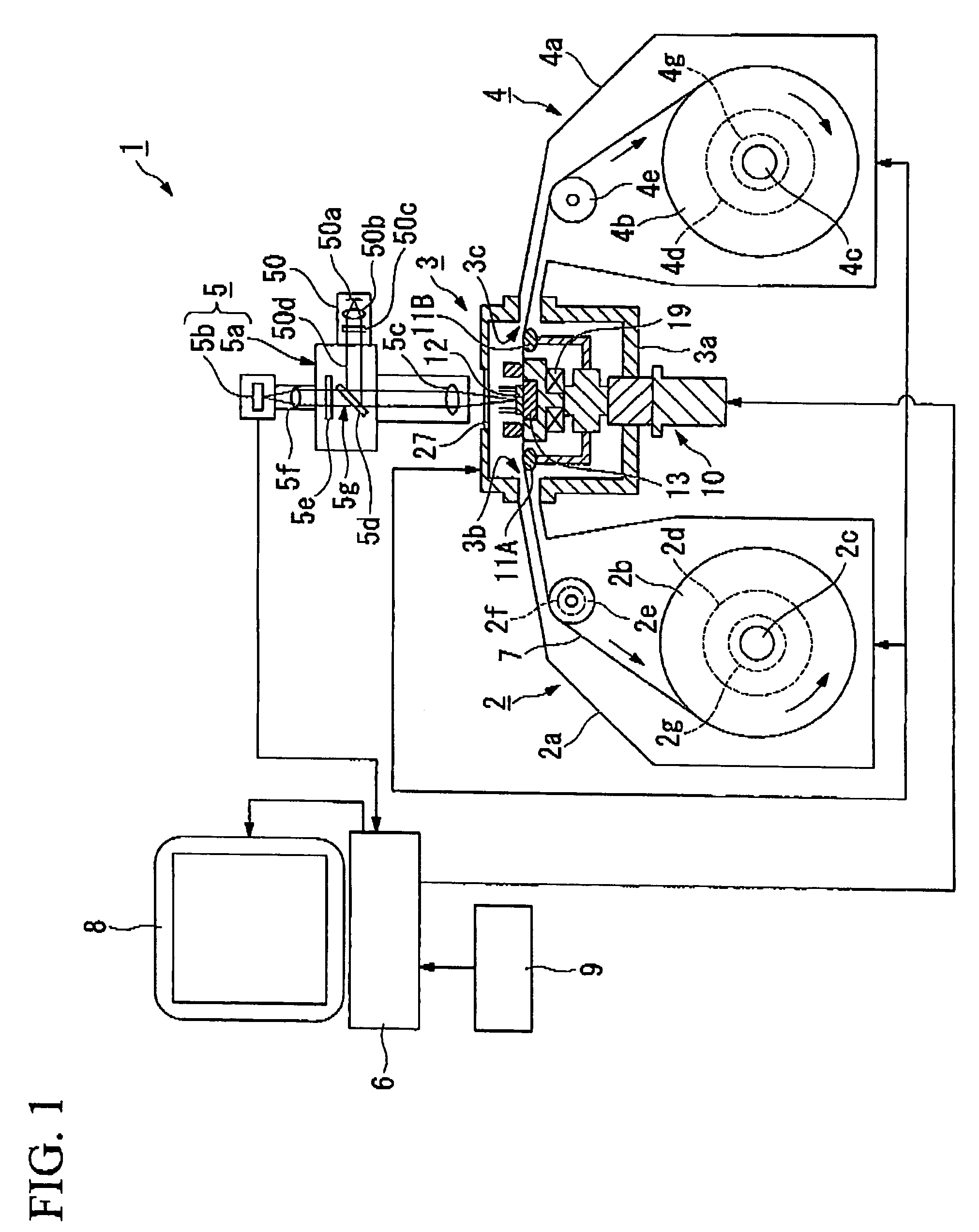
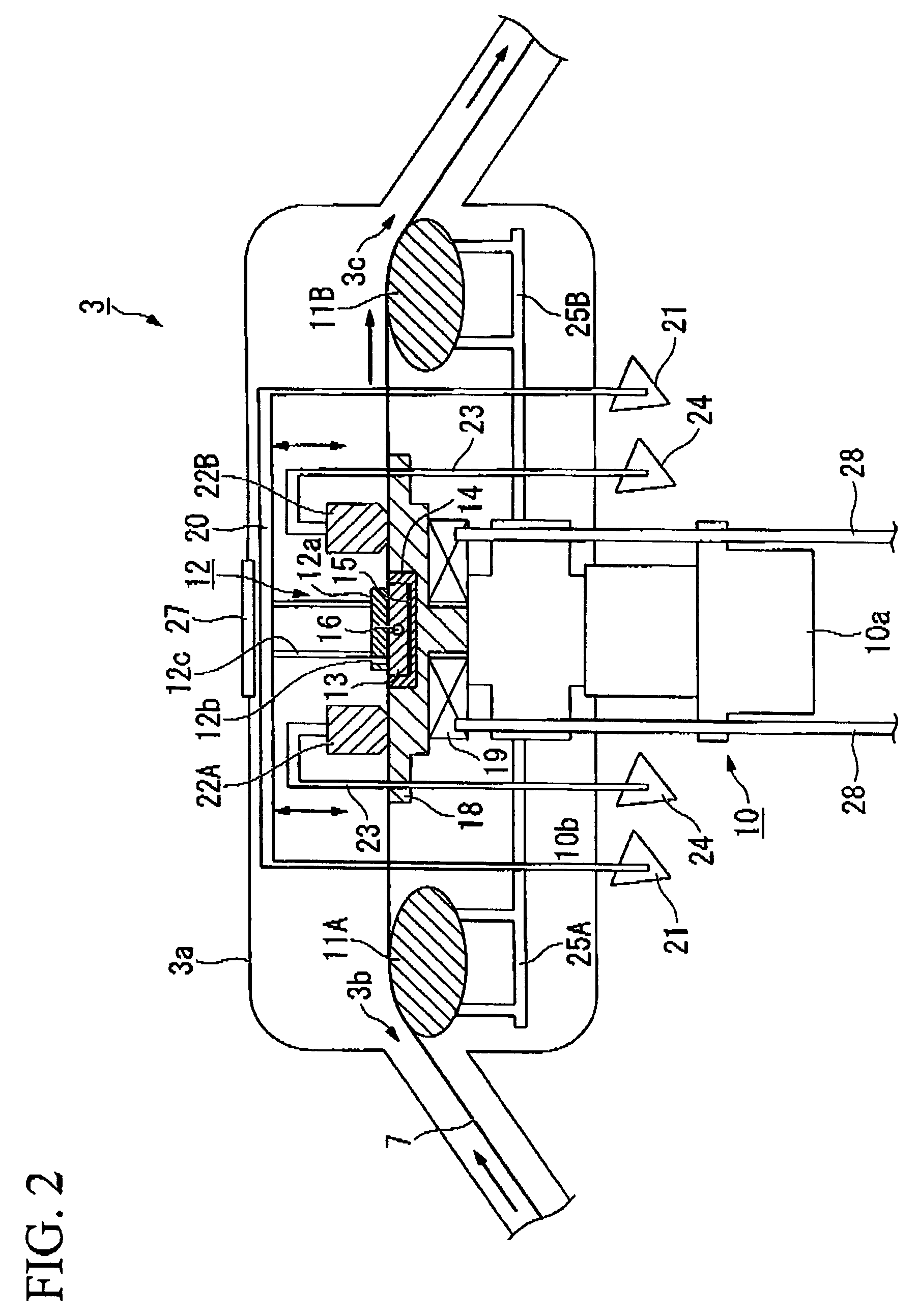
[0055]FIG. 1 is a schematic sectional view for explaining a schematic structure of the continuous observation apparatus of magnetic flux distribution according to an embodiment of the present invention. FIG. 2 is a schematic sectional view for explaining a principal part of the structure of the continuous observation apparatus of magnetic flux distribution according to the embodiment of the present invention. FIGS. 3A and 3B are respectively a plan view for explaining a schematic structure of a magneto-optical indicator film retaining portion used in the continuous observation apparatus of magnetic flux distribution according to the embodiment of the present invention and a sectional view taken along line A-A sh...


PUM

PropertyMeasurementUnit
widthaaaaaaaaaa
widthaaaaaaaaaa
thicknessaaaaaaaaaa

Abstract

A continuous observation apparatus of magnetic flux distribution in which a long sample containing a superconducting material or magnetic material is transferred to an observation position and magnetic flux is observed sequentially at each of certain areas along a longitudinal direction of the sample is provided. A method of continuously observing magnetic flux by which a long sample containing a superconducting material or magnetic material is transferred to an observation position and magnetic flux is observed sequentially at each of certain areas along a longitudinal direction of the sample is also provided.

Description

BACKGROUND OF THE INVENTION[0001]1. Field of the Invention[0002]The present invention relates to a continuous observation apparatus and method of magnetic flux distribution. More particularly, the invention relates to a continuous observation apparatus and method of magnetic flux distribution such as that for a non-destructive characterization on defects of long superconducting wires and tapes used in power cables, magnets and apparatuses such as motors and generators or that for assessing critical current density or long magnetic tapes.[0003]Priority is claimed on Japanese Patent Application No. 2005-258291, filed Sep. 6, 2005, the content of which is incorporated herein by reference.[0004]2. Description of the Related Art[0005]Where there are defects such as micro cracks or existence of secondary phases and etc. inside a superconducting material, it is conventionally known that a weak coupling region will allow an external magnetic flux to penetrate into the superconducting materi...

Claims


Application Information

Patent Timeline
Patent Type & Authority Patents(United States)
IPC IPC(8): G01N27/82G01R33/032
CPCG01R33/1253G01R33/1238
Inventor MACHI, TAKATOCHIKUMOTO, NORIKONAKAO, KOICHIFUJI, HIROSHIKITOH, YUTAKAIZUMI, TERUOSHIOHARA, YUH
Owner FUJIKURA LTD
Why Eureka
Try Eureka