
Dynamic and differential CMOS logic with signal-independent power consumption to withstand differential power analysis

a technology of differential power analysis and dynamic cmos logic, which is applied in logic circuits using specific components, pulse techniques, instruments, etc., can solve the problems of low side channel information, easy tampering, and inability to operate without encryption technology and a secure implementation of encryption technology, etc., and achieves no satisfactory protection against attacks based on dpa. the effect of reducing the risk of tampering

Inactive Publication Date: 2008-08-26
RGT UNIV OF CALIFORNIA
View PDF5 Cites 46 Cited by
  • Summary
  • Abstract
  • Description
  • Claims
  • Application Information

AI Technical Summary

Benefits of technology

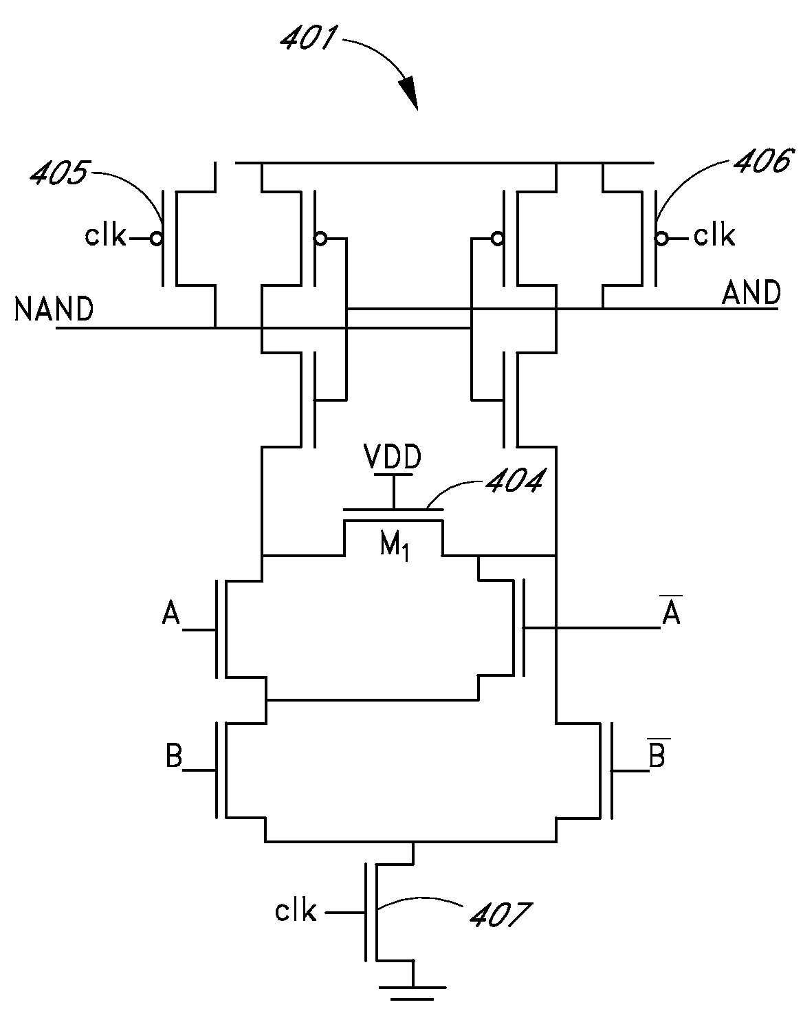
The present invention provides logic that has relatively independent power consumption from logic transitions. This is achieved by measuring logic values by charging and discharging capacitors using a relatively fixed amount of energy for each transition. The logic style is called Sense Amplifier Based Logic (SABL) and it achieves this by switching the output independently of the input sequence and by having a relatively constant load capacitance. The SABL gate is realized by providing a sense amplifier half of a flip-flop and replacing an input differential pair by a Differential Pull Down Network (DPDN). The DPDN connects all internal nodes to one of the output nodes, making the total output capacitance a constant. The logic style is a combination of dynamic and differential logic, and it achieves relatively constant power consumption regardless of the input statistics. The logic can be implemented using various logic tools and techniques.

Problems solved by technology

Electronic banking, e-commerce, virtual private networks and so on cannot operate without encryption technology and a secure implementation of the encryption technology.
These procedures merely lower the side channel information and might easily be disabled through tampering.
None of the above methods provide satisfactory protection against attacks based on DPA.

Method used


Image

  • Dynamic and differential CMOS logic with signal-independent power consumption to withstand differential power analysis
  • Dynamic and differential CMOS logic with signal-independent power consumption to withstand differential power analysis
  • Dynamic and differential CMOS logic with signal-independent power consumption to withstand differential power analysis

Examples


Embodiment Construction

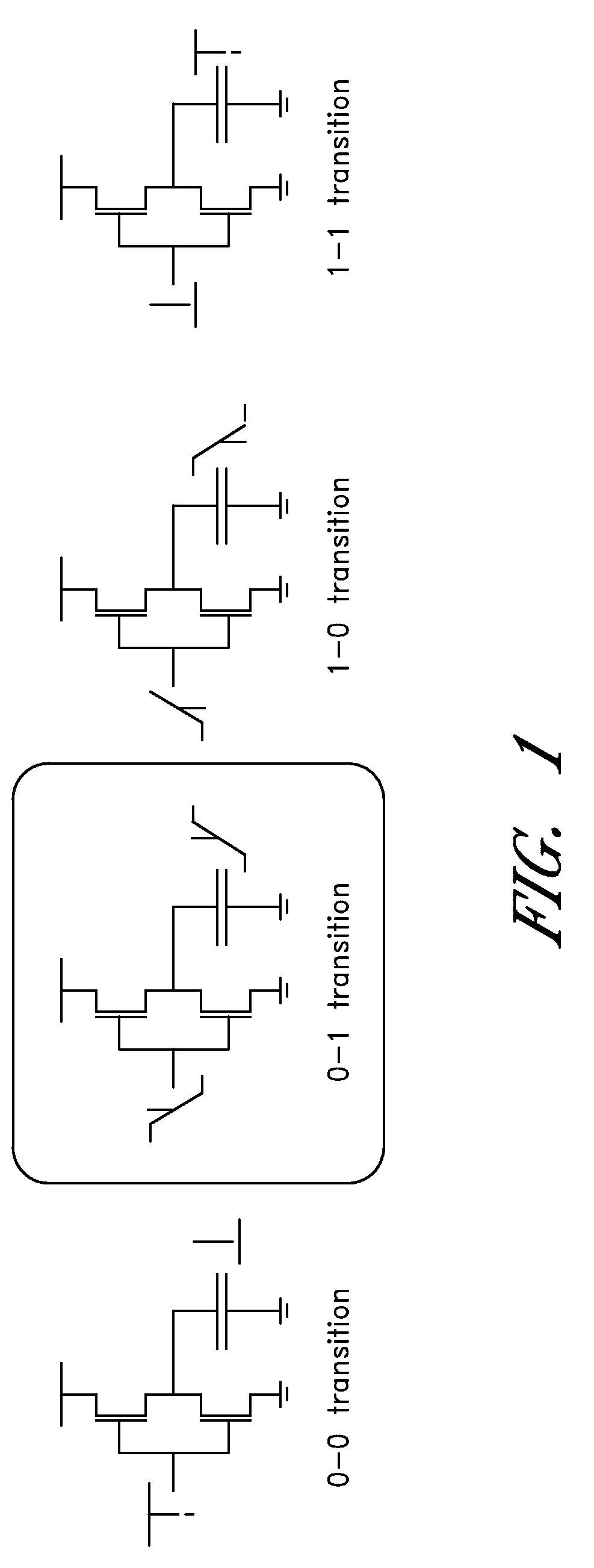
[0032]As shown in FIG. 1, Static Complementary CMOS logic (scCMOS), which is the default logic style in standard cell libraries used for security ICs only consumes energy from the power supply when its output has a 0-1 transition. During the 1-0 transition, the energy previously stored in the output capacitance is dissipated. In the two degenerated events of 0-0 or a 1-1 transition no power is used. This asymmetric power profile provides the information used in DPA to find the secret key.

[0033]The logic style disclosed herein with data-independent power consumption does not reveal this information. In one embodiment, logic values are measured by charging and discharging capacitors using a fixed amount of energy for every transition. In one embodiment, even though different capacitances are switched, the logic style provides the property of charging in every cycle a total capacitance with a constant value. The disclosed Sense Amplifier Based Logic (SABL) achieves this goal by (1) swi...


PUM


Abstract

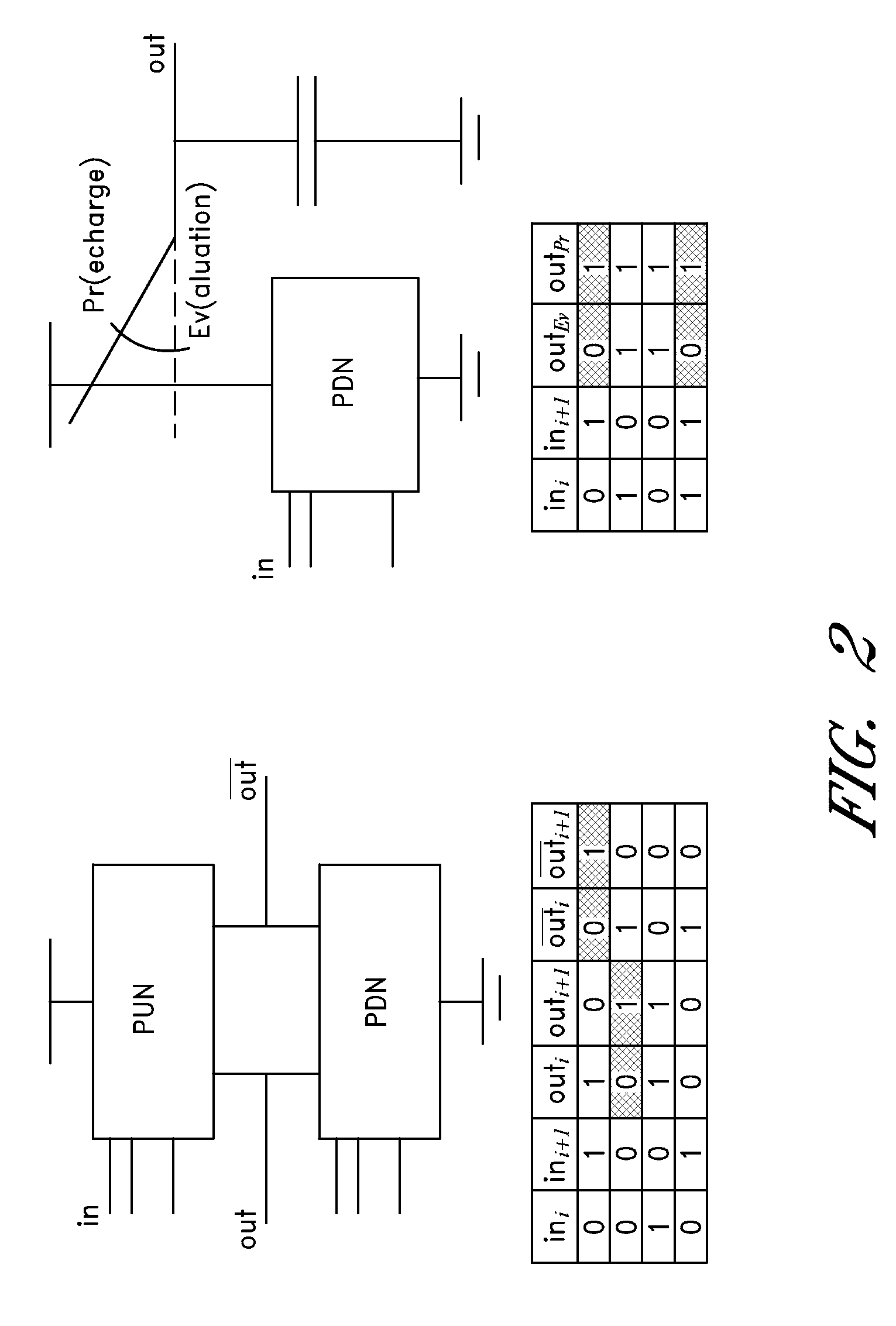
A dynamic and differential CMOS logic style is disclosed in which a gate uses a fixed amount of energy per evaluation event. The gate switches its output at every event and loads a constant capacitance. The logic style is a Dynamic and Differential Logic (DDL) style. The DDL style logic typically has one charging event per clock cycle and the charging event does not depend on the input signals. The differential feature masks the in-put value because a precharged output nodes is discharged during the evaluation phase. The dynamic feature breaks the input sequence: the discharged node is charged during the subsequent precharge phase.

Description

REFERENCE TO RELATED APPLICATIONS[0001]The present application claims priority benefit of U.S. Provisional Application No. 60 / 504,380, filed Sep. 17, 2003, titled “A DYNAMIC AND DIFFERENTIAL CMOS LOGIC WITH SIGNAL INDEPENDENT POWER CONSUMPTION TO WITHSTAND DIFFERENTIAL POWER ANALYSIS FOR SMART CARDS,” the entire contents of which is hereby incorporated by reference.GOVERNMENT INTEREST STATEMENT[0002]This invention was made with Government support of Grant No. 0098361, awarded by the NSF. The Government has certain rights in this invention.BACKGROUND[0003]1. Field of the Invention[0004]The present invention relates to logic and methods for signal-independent power consumption to withstand differential power analysis and other side-channel attacks.[0005]2. Description of the Related Art[0006]Electronic banking, e-commerce, virtual private networks and so on cannot operate without encryption technology and a secure implementation of the encryption technology. To obtain security, many s...

Claims


Application Information

Patent Timeline
Patent Type & Authority Patents(United States)
IPC IPC(8): H03K19/20H03K19/094G07F7/10H03K19/173
CPCG06Q20/341G07F7/082H03K19/1738G11C7/24H03K19/018528G07F7/1008
Inventor VERBAUWHEDE, INGRID M.TIRI, KRIS J. V.
Owner RGT UNIV OF CALIFORNIA
Learn More