Fiber optic categorization and management tray

a technology of fiber optics and management trays, applied in the direction of optics, instruments, optical light guides, etc., can solve the problems of limited space, challenge, and limited attempts in many aspects, and achieve the effects of improving the state-of-the-art in management, facilitating routing, and improving protection for network expansion

Inactive Publication Date: 2008-08-26
GONZALES CURTIS PAUL +1
View PDF22 Cites 135 Cited by
  • Summary
  • Abstract
  • Description
  • Claims
  • Application Information

AI Technical Summary

Benefits of technology

[0015]The present invention improves the state-of-the-art in the management of fiber optic field cabling infrastructure. The described invention is a multilevel folding fiber management tray, which enables easier routing and improved protection for network expansion. A folding tray that is generally planar when in its open position provides space for more fiber network components than does a stack of trays while also improving the routing of the fibers. Additionally, the preferred embodiment which uses three trays in a tri-fold configuration allows for separation of fiber categories into groups of Forward, Reverse, and Control, like that used in the deep fiber architecture of Aurora Networks. In another embodiment the three trays may be used at the interface between copper and optical fiber for segregation of Hybrid, Fiber and Coax (Copper), an HFC architecture. Furthermore, provision is made for segregating active (Light) fibers from those that are inactive (Dark). Having separate categorization trays improves the routing of fibers by allowing the active networks to be placed in a protected region at the bottom of the tray where they will not be disturbed as new networks are activated. This feature improves reliability for active networks.

Problems solved by technology

However, access to broadband transmissions at the 640-kbps capacity of DSL only served to whet the appetites of consumers of data who have come to demand even higher rate feeds as more applications are developed to access and use more and more data, such as HDTV and video on demand.
This attempt is challenged and limited in many regards.
Though a splice tray must permit the supportive mounting and protection of individual splices and storage of the slack optical fibers in a relatively neat configuration, space is limited.
Bending a fiber more sharply than a certain radius will, at first, result in increased attenuation of the optical signal.
A stack of splice trays that are so configured offers some capability for segregating buffer tubes from one tray to another, but provides no assistance for organizing fibers once removed from the buffer tube.
Such a system of stacked trays limits access to one tray at a time.
A disadvantage of such a system is that access to the fibers contained by any particular tray is restricted by the extent to which other trays within the stack may be folded out of the way or the working tray may be removed from the stack, without over-bending any of the fibers.
Once an optical network has been activated, however, handling of a single delicate fiber that is feeding a large number of subscribers carries a significant exposure to liability which often corresponds to very large insurance premiums paid by those technicians who work in trays containing active fibers.
Furthermore, service providers are at risk of dissatisfying customer with unscheduled outages if fibers are broken.

Method used


Image

  • Fiber optic categorization and management tray
  • Fiber optic categorization and management tray
  • Fiber optic categorization and management tray

Examples


Embodiment Construction

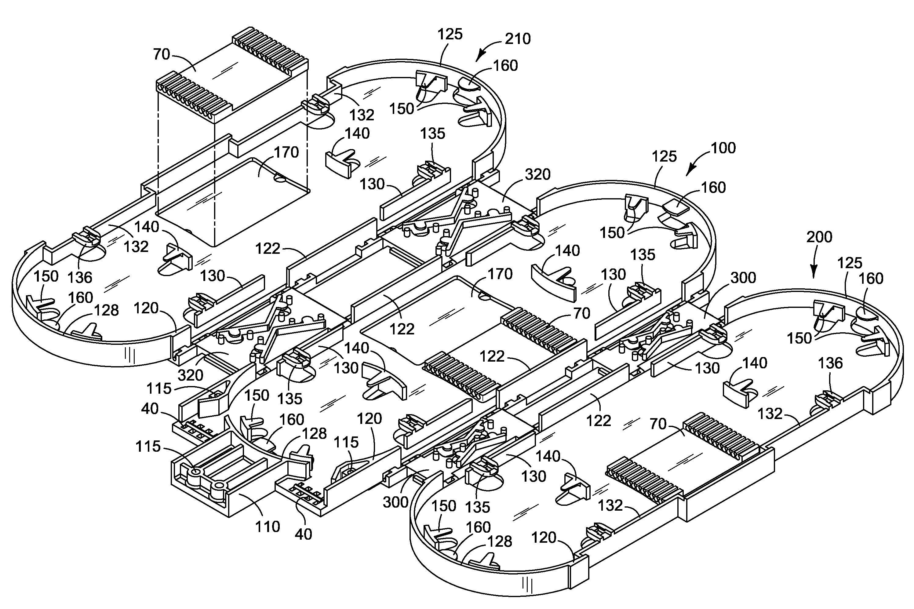
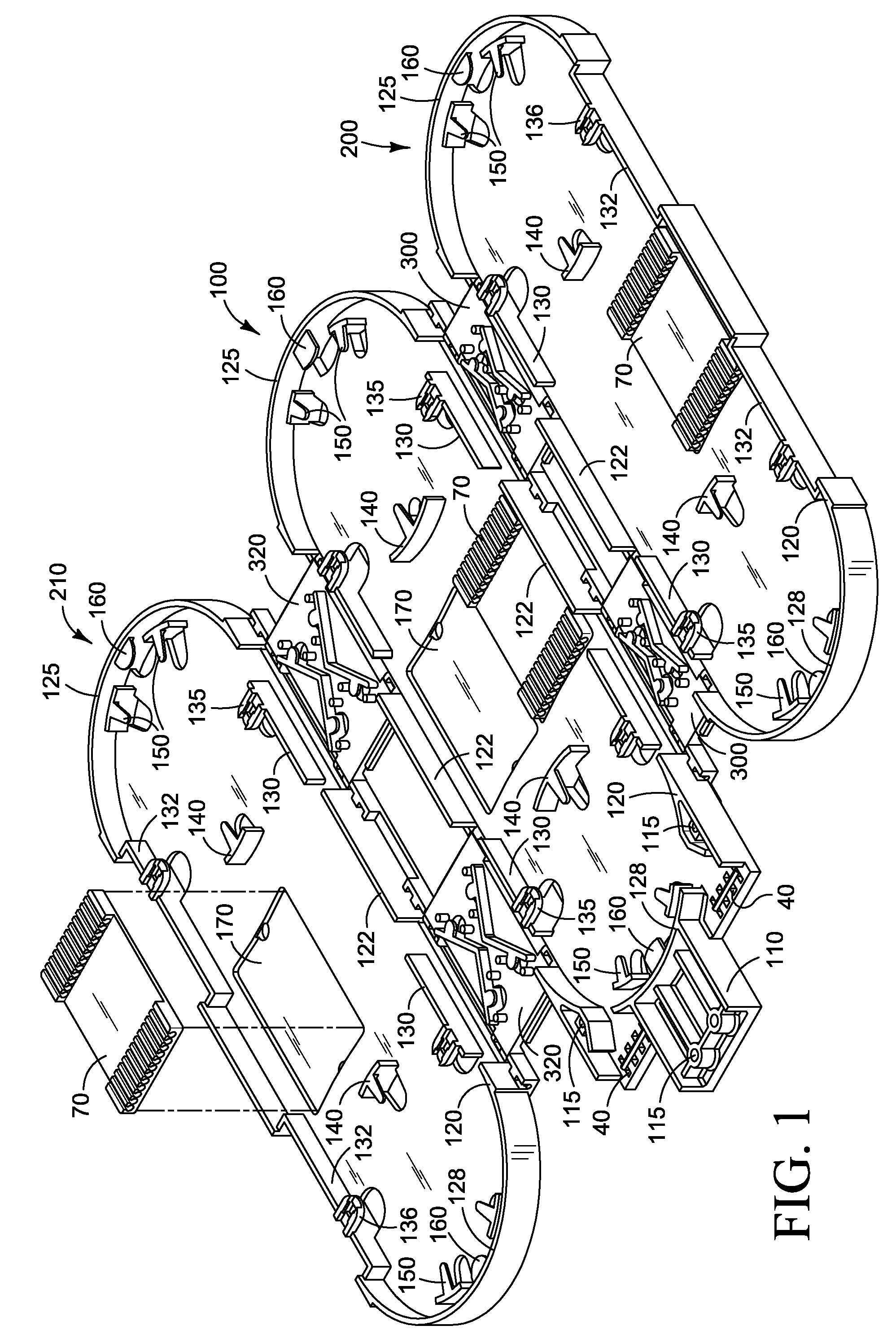
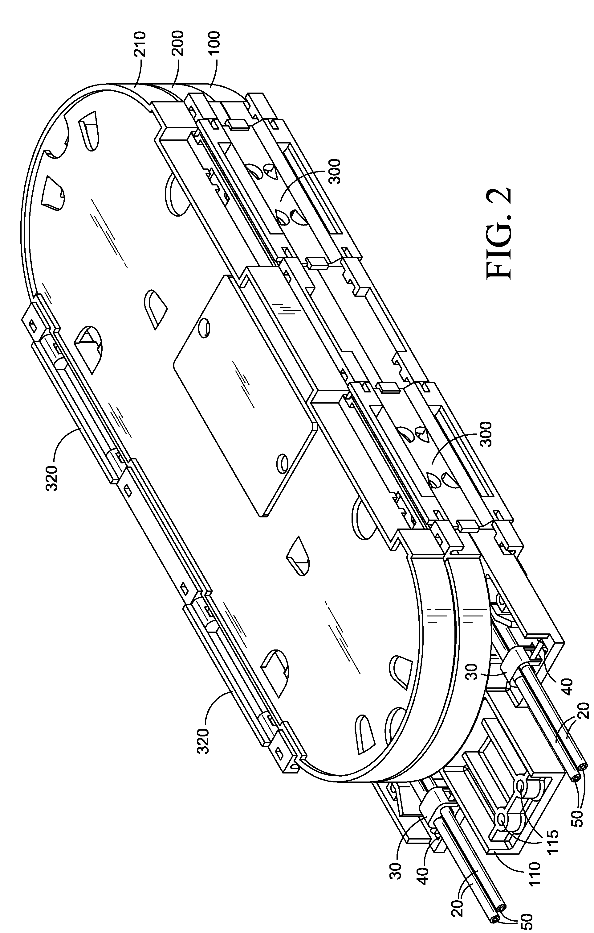
[0068]The categorization and management system of the present invention will now be described in detail beginning with reference to FIG. 1. Assembly of the system in its preferred embodiment begins with a base tray 100 that is hingedly connected on its right to a second, right-hand tray 200, and on the left to a third, left-hand tray 210. The connections between the base and right-hand trays are provided by hinges 300, while hinges 320 connect the left-hand tray 210 to the base tray 100. All connections between hinges and trays are provided by pins 302.

[0069]The right-hand tray 200 and the left-hand tray 210 are identical to one another, differing only in that they have been rotated within their planes by 180° from one another. With the exception of the mounting bracket 110 and strain relief elements 40, the outer trays 200 and 210 have the same features as the base tray 100. It is to be noted that, in one alternate embodiment, a smaller organizer can be constructed using only two t...


PUM


Abstract

A fiber optic splice organizer stores optical fiber splices and sufficient slack to permit the fibers to be readily separated, such as for reorganization or to remake a splice. Multiple hinges connect a plurality of fiber trays side by side to provide pivotable connections between trays. A flat orientation of the trays enables splicing and coiling of fibers as they are loaded into a tray. The trays then pivot into a fiber storage position. Special features of the hinges provide support for fibers and splices as they are loaded into the trays. The hinges protect the fibers as the trays are pivoted as well as when the trays are in their folded position for storage without requiring buffer tubes. Multiple architectures for the organization of fibers are enabled without violating minimal bend radii, and while providing for ease of separation of individual fibers or groups of fibers.

Description

CROSS-REFERENCES TO RELATED APPLICATIONS[0001]Not Applicable.STATEMENT REGARDING FEDERALLY SPONSORED RESEARCH OR DEVELOPMENT[0002]Not Applicable.FIELD OF THE INVENTION[0003]The present invention relates generally to a system of support for splicing of optical fibers from fiber optic cables. More particularly, the present invention relates to an assembly of hinged trays for organizing optical fibers, positioning them for proper coupling, for categorizing them into functional groups, and for storing associated excess cable.BACKGROUND OF THE INVENTION[0004]With rapid growth in customer demand for ever-increasing bandwidth to support transmission of interactive voice, video and data, the telecommunications industry has outgrown the capability of copper wire. The hunger for a supply of information at first moved slowly from the 56-kbps rate offered by dial-up modems to the greater bandwidth offered by DSL. However, access to broadband transmissions at the 640-kbps capacity of DSL only se...

Claims


Application Information

Patent Timeline
Patent Type & Authority Patents(United States)
IPC IPC(8): G02B6/36G02B6/00
CPCG02B6/4471G02B6/4455
Inventor GONZALES, CURTIS PAULBROWN, TONY L.
Owner GONZALES CURTIS PAUL
Why Eureka
Try Eureka