Display device with image sensing device

a technology of image sensing and display device, which is applied in the direction of radiation control device, printer, identification means, etc., can solve the problems of high manufacturing cost, awkwardness, and odd feeling, and achieve the effects of low cost, simple arrangement, and high pixel density

Inactive Publication Date: 2008-09-02
CANON KK
View PDF19 Cites 29 Cited by
  • Summary
  • Abstract
  • Description
  • Claims
  • Application Information

AI Technical Summary

Benefits of technology

[0010]Therefore, the present invention has been made in consideration of the above problems and has as its object to provide a display device with an im

Problems solved by technology

For this reason, the partner's face displayed on the display means gazes another place, thus feeling awkward if they talk with each other, and feeling odd compared to a face-to-face conversation.
Also, the image sensing device and display device must be independently manufactured and assembled as independent devices, resulting in high manufacturing cost.
(1) The number of pixels of a sensed image is nearly equal

Method used


Image

  • Display device with image sensing device
  • Display device with image sensing device
  • Display device with image sensing device

Examples


first embodiment

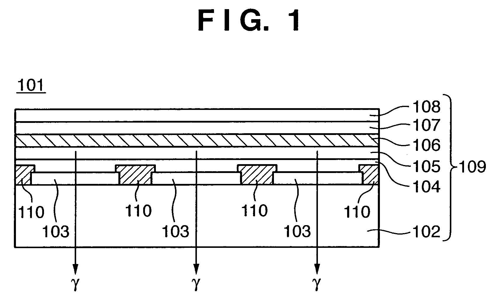
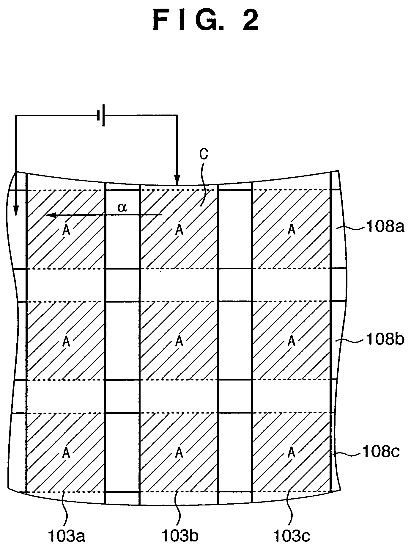
[0058]The first embodiment is an example using an organic EL (EL: Electro Luminescence) element as display means. The organic EL element is a self-emission element, and has excellent features: (1) high light-emitting efficiency; (2) a low driving voltage; (3) various colors (green, red, blue, yellow, and the like) can be displayed by selecting light-emitting materials; (4) no backlight is required; (5) no dependence on the field angle due to surface emission; (6) low-profile and lightweight; and so forth, when it is used in a display device. Hence, a display device using an organic EL element has received a lot of attention as a display device that replaces a CRT and LCD. Prior to a description of this embodiment, an organic EL display device will be explained.

[0059]Dot-matrix organic EL display devices which make display by means of dots arranged in a matrix are classified into a simple matrix system and active matrix system.

[0060]The simple matrix system externally and directly dr...

second embodiment

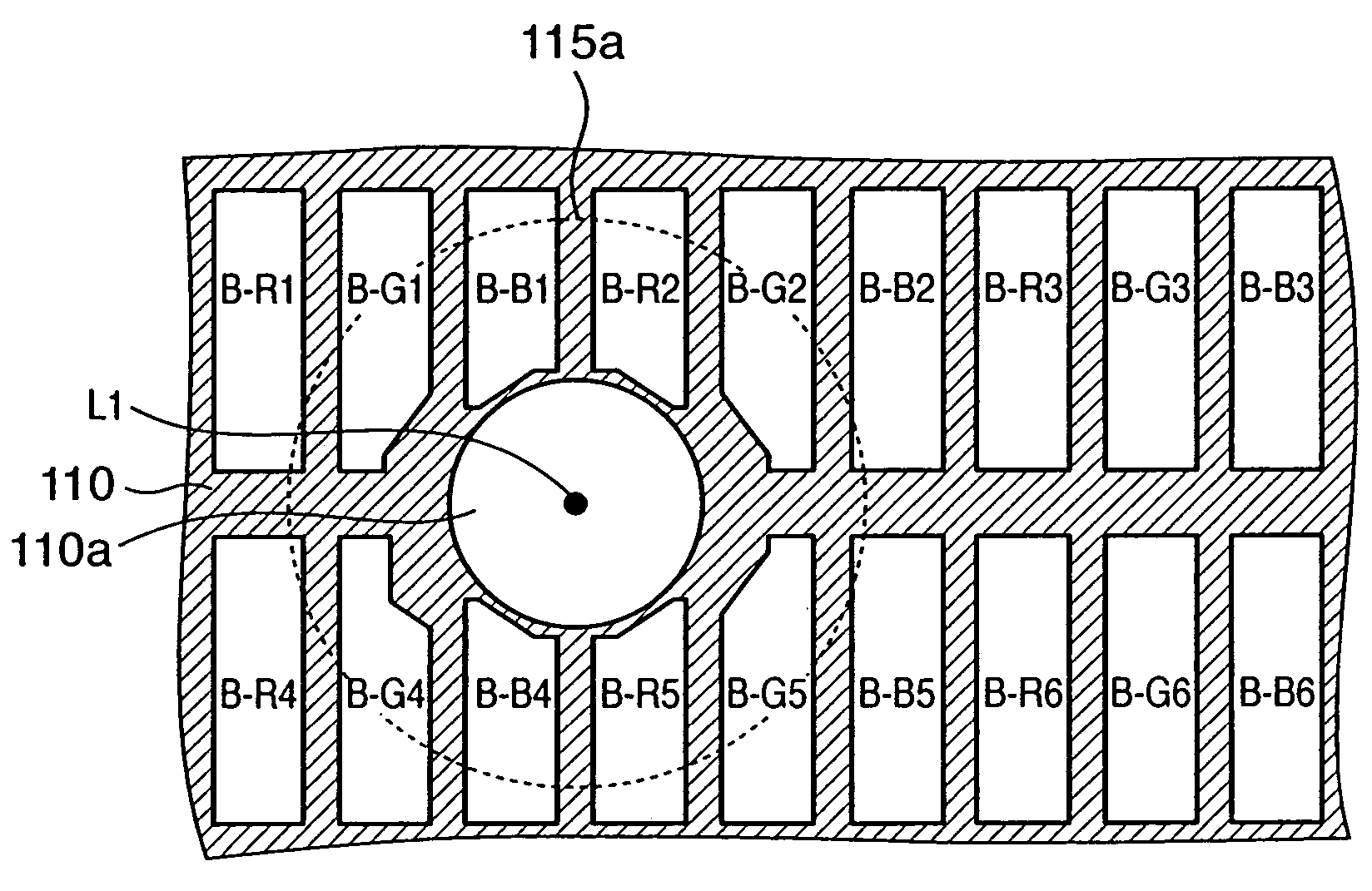
[0135]The second embodiment is a modification of the first embodiment. In this embodiment, display pixels are arranged at higher density to improve the display resolution, and even when the opening ratio of each display pixel is increased, a relatively large aperture stop diameter can be assured.

[0136]FIGS. 15 and 16 show an example of full-color display means which comprises image sensing means: FIG. 15 is a plan view of the display means 113 of the second embodiment when viewed from the anode 103 side, and FIG. 16 is a plan view of the display means 113 of the second embodiment when viewed from the cathode 108 side. FIGS. 15 and 16 respectively correspond to FIGS. 5 and 6 of the first embodiment. Note that FIG. 15 does not illustrate members other than the anodes 103 and cathodes 108, and FIG. 16 does not illustrate members other than the black matrix 110. Note that all of the five full-color methods described in the first embodiment can be applied to this embodiment.

[0137]Referri...

third embodiment

[0145]The third embodiment will exemplify a case wherein a high-resolution sensed image can be obtained using an image sensing device which performs pixel shift by a multi-eye optical system without increasing the thickness of the overall device.

[0146]As an image sensing device which performs pixel-shift image sensing by a multi-eye optical system, an image sensing device disclosed in Japanese Patent Laid-Open No. 2002-209226 is known. This image sensing device forms four object images by four lenses, and senses these images by four image sensing regions. At this time, the four image sensing regions sample positions which are respectively shifted by ½ pixels, perform pixel-shift image sensing. The four image sensing regions sample object images of different wavelength ranges, and when these images are composited, an image equivalent to a known Bayer matrix can be obtained. This embodiment uses this image sensing device as the image sensing means 112.

[0147]FIG. 17 is a partially enla...


PUM


Abstract

The object of this invention is to provide a display device with an image sensing device, which can match lines of sight by a simple arrangement and realize a high pixel density, low cost and low profile. To this end, the display device with an image sensing device has a display unit that includes a plurality of display pixels, a light-shielding member arranged between neighboring display pixels, and an image sensing unit arranged on a back portion of the display unit; the light-shielding member has an opening for guiding light toward the image sensing unit and the image sensing unit has an imaging lens at a position corresponding to the opening.

Description

FIELD OF THE INVENTION[0001]The present invention relates to a display device with an image sensing device, in which an image sensing device is integrally provided to a relatively low-profile display device such as an organic EL, liquid crystal, plasma system, or the like and, more particularly, to a display device with an image sensing device, which is suitably used in real-time, two-way communications using a video phone or the like.BACKGROUND OF THE INVENTION[0002]In recent years, remarkable development of communication networks allows real-time, two-way communications using video phones or the like. The video phone comprises image sensing means for converting an object image into an electrical image signal, and display means for converting the electrical image signal into an optical signal, and displaying that optical signal. The user of the video phone talks while observing the partner's face displayed on the screen of the display means. At the same time, the image of the user'...

Claims


Application Information

Patent Timeline
IPC IPC(8): H04N5/222H04N5/262G02F1/1333H01L51/50G03B29/00G06F3/041G09F9/30G09G3/20G09G3/30H01L27/146H01L27/32H01L51/52H04N1/028H04N5/225H04N5/335H04N5/369H04N5/374H04N5/66H04N7/14
CPCG06F3/0412H01L27/146H01L27/14623H01L27/14627H01L27/3234H04N7/144H04N5/2253H01L27/3281H01L51/5237H01L51/5284H01L27/3244G06F3/042G09G3/3208G09G2354/00G09G2360/141G09G5/14G09G2300/0426H04N23/54H10K59/65H10K59/12H10K59/17H10K50/8428H10K50/844H10K50/865
Inventor YAMASAKI, RYO
Owner CANON KK
Why Eureka
Try Eureka