Split aperture array for increased short range target coverage

a short-range target and aperture array technology, applied in the field ofradar systems, can solve the problems of significant limitations in the processing and implementation of conventional radar systems, and require much greater processing and response time, and achieve the effect of enhancing short-range target coverag

Inactive Publication Date: 2008-09-09
LOCKHEED MARTIN CORP
View PDF10 Cites 55 Cited by
  • Summary
  • Abstract
  • Description
  • Claims
  • Application Information

AI Technical Summary

Benefits of technology

[0007]The invention takes advantage of the signal excess characteristic of short range targets to effectively increase the number of look opportunities for such short range targets.
[0008]According to an aspect of the present invention, a radar array having a plurality of configurable radiating elements, which plurality defines a common aperture A of the array, is electronically segmented or sectored into two independently steerable arrays, each having an aperture substantially half of the common aperture A. The two independently steerable arrays are configured vertically one on top of the other and processed separately in order to effectively double the elevation beamwidths in both the transmit and receive beams without the need to spoil the beam, while also doubling the number of beams that can be used, thereby effectively doubling the target revisit rate.

Problems solved by technology

However, even with SR pulses, significant limitations exist in conventional radar systems processing and implementation.
However, the problem lies with the number of look opportunities with which to detect, track and localize a target with sufficient accuracy to evaluate a projectile launch or impact point.
A radar system utilizing a narrow beam long range pulse for detecting and tracking targets may operate quite effectively for long range objects; however, such a system may be inadequate to track short range objects having high target vertical velocities, which require much greater processing and response time, but which does not require such narrow beam(s).

Method used


Image

  • Split aperture array for increased short range target coverage
  • Split aperture array for increased short range target coverage
  • Split aperture array for increased short range target coverage

Examples


Embodiment Construction

[0017]It is to be understood that the figures and descriptions of the present invention have been simplified to illustrate elements that are relevant for a clear understanding, while eliminating, for the purpose of clarity, many other elements found in radar systems and methods of making and using the same. Those of ordinary skill in the art may recognize that other elements and / or steps may be desirable in implementing the present invention. However, because such elements and steps are well known in the art, and because they do not facilitate a better understanding of the present invention, a discussion of such elements and steps is not provided herein.

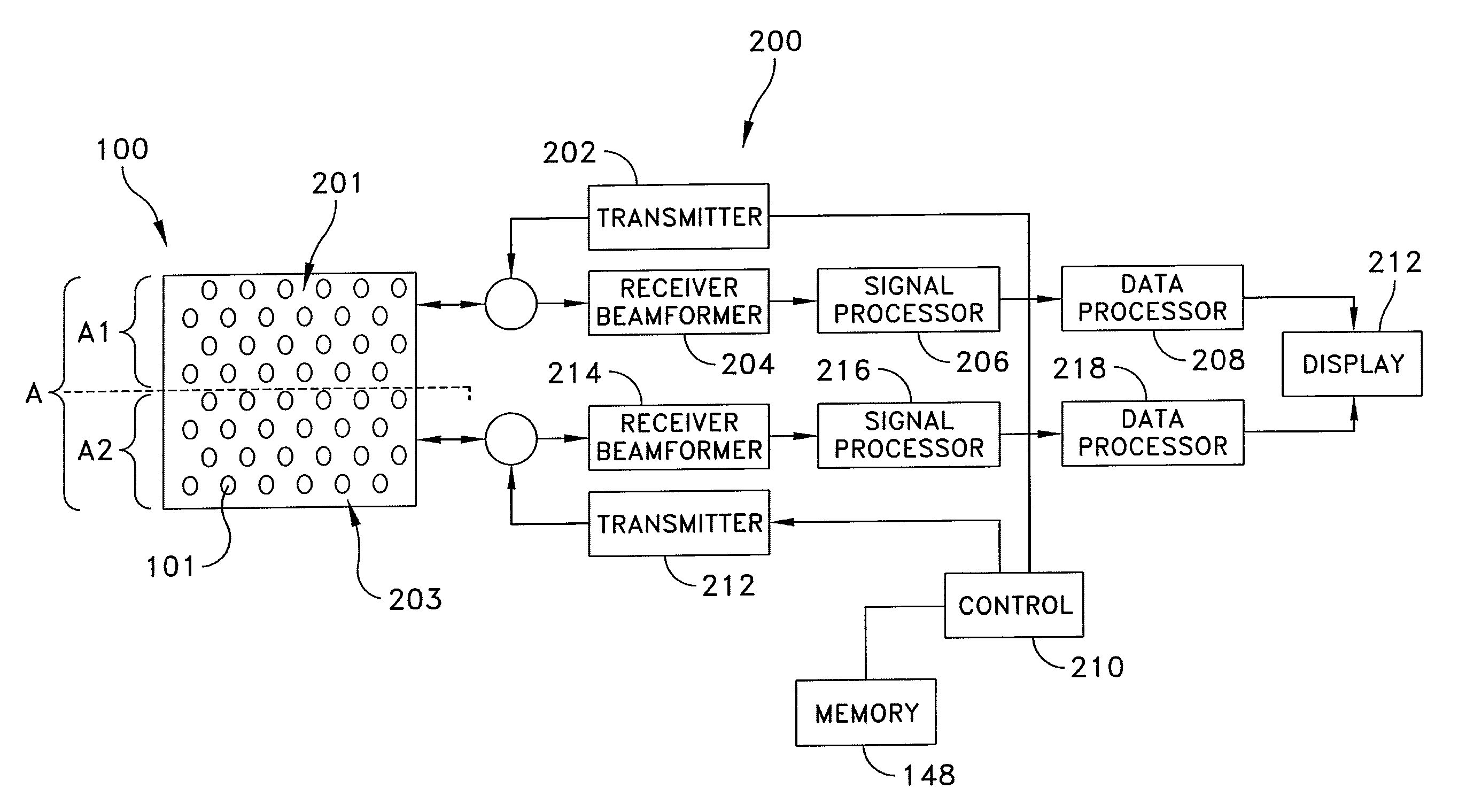
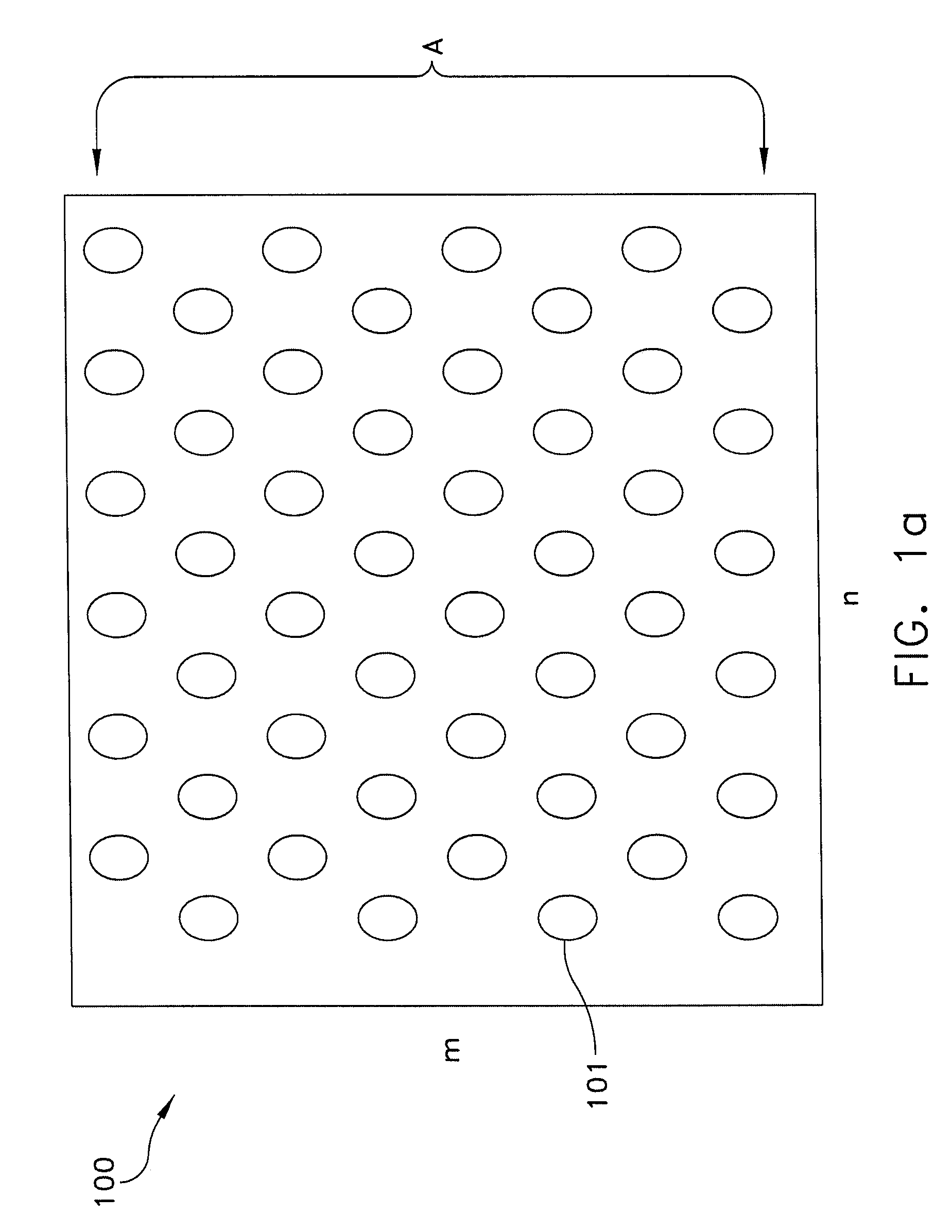
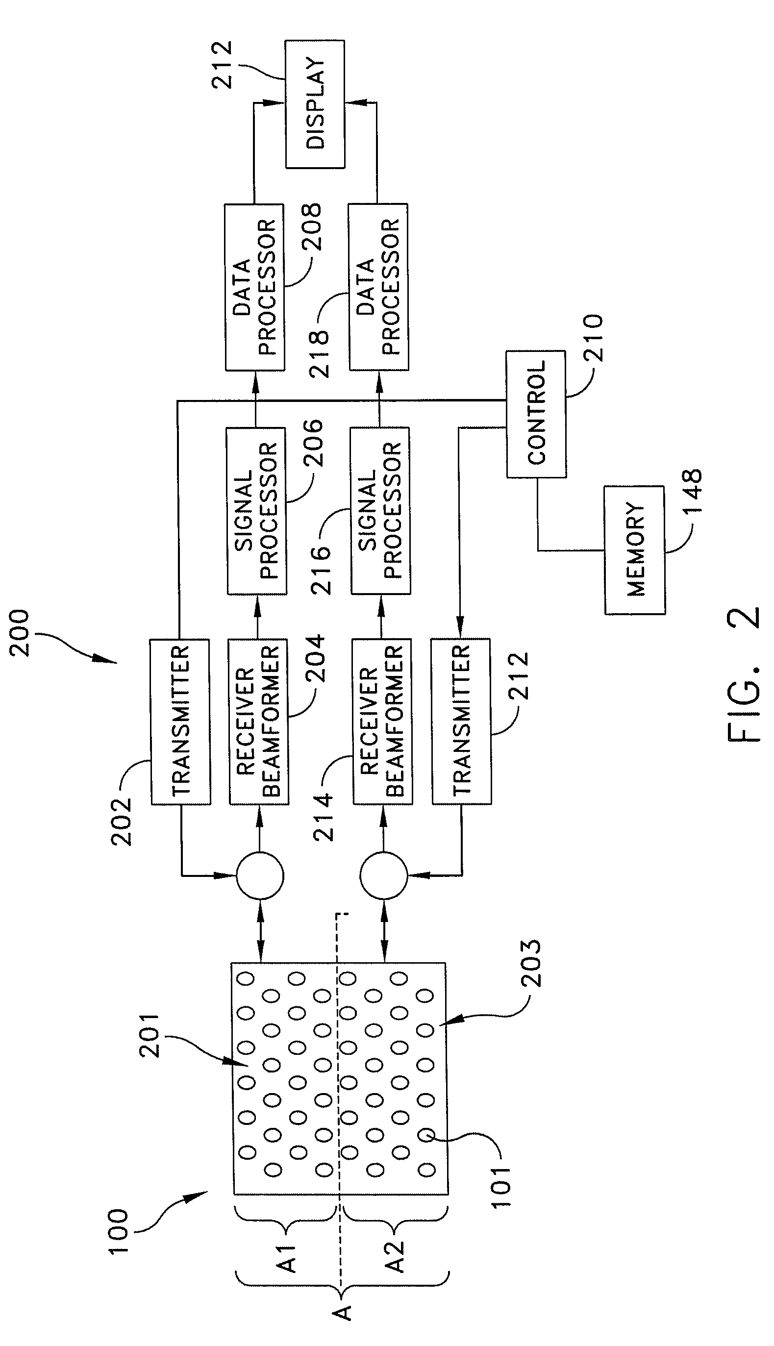
[0018]Referring now to FIG. 1a, there is shown a front view of a phase array antenna system 100 having an aperture A shown by way of example and not limitation, and including a rectangular array of m×n antenna elements 101 arranged in rows and columns. The antenna elements are each associated with respective transmit / receive (T / R) mo...


PUM


Abstract

A phased array radar system comprising a plurality of radiating elements configured in a common array aperture for detecting and tracking targets; and a transmit and receive arrangement responsive to a first control signal for configuring the plurality of radiating elements to define a plurality of sub-apertures from the common array aperture for detecting and tracking short range targets, wherein the plurality of sub-apertures are independently steerable array apertures.

Description

FIELD OF INVENTION[0001]The present invention relates generally to radar systems and more specifically to a system and method for enabling short range array antenna coverage without significantly impacting long range performance.BACKGROUND[0002]The detection and tracking of a target object or objects is typically accomplished with radio detection and ranging, commonly known as radar. Radar systems typically emit electromagnetic energy and detect the reflection of that energy scattered by a target object. By analyzing the time difference of arrival, Doppler shift, and various other changes in the reflected energy, the location and movement of the target object can be calculated. Phased array antenna systems employ a plurality of individual antenna elements or subarrays of antenna elements that are separately excited to cumulatively produce a transmitted electromagnetic wave that is highly directional. The radiated energy from each of the individual antenna elements or subarrays is of...

Claims


Application Information

Patent Timeline
Patent Type & Authority Patents(United States)
IPC IPC(8): G01S13/00
CPCG01S7/03G01S13/426H01Q25/02H01Q21/08G01S2013/0272G01S2013/0254
Inventor TIETJEN, BYRON W.
Owner LOCKHEED MARTIN CORP
Why Eureka
Try Eureka