Common path frequency domain optical coherence reflectometry/tomography device

a frequency domain optical coherence reflectometer and frequency domain optical coherence tomography technology, applied in measurement devices, scientific instruments, instruments, etc., can solve problems such as difficult or even impossible to obtain reference reflection from the vicinity, reference reflection cannot be obtained from a point located far from the sample, and limitation becomes especially importan

Inactive Publication Date: 2008-09-23
IMALUX CORP
View PDF7 Cites 83 Cited by
  • Summary
  • Abstract
  • Description
  • Claims
  • Application Information

AI Technical Summary

Benefits of technology

[0018]In accordance with the present invention, there are provided improved common path frequency domain OCR / OCT devices that use the advantages of a common path optical interferometer design together with the advantages of frequency domain registration of the optical spectrum of the combined reference and sample portions of the optical radiation, overcoming at the same time limitations of both approaches.
[0037]Thus, in accordance with the subject invention, unlike previously known common path frequency domain OCT / OCR devices, optical radiation from a source is first split into two replicas by a portion of optical fiber with predetermined optical properties adapted for producing two eigen modes of the optical radiation propagating therethrough with a predetermined optical path length difference. The two replicas of the optical radiation outgoing from the portion of the optical fiber are then delivered to an associated sample by a delivering device, the delivering device being, preferably, an optical fiber probe. The tip of the optical fiber of the optical fiber probe serves as a reference reflector and also serves as a combining element that produces a combination optical radiation by combining an optical radiation returning from the associated sample with a reference optical radiation reflected from the reference reflector. The topology of the devices of the subject invention allows for registering a cross-polarized component of the optical radiation reflected or backscattered from the associated sample, as well as a parallel-polarized component. Having the optical path length difference for the two eigen modes of the optical radiation (which is an equivalent of an interferometer offset in previously known devices) differ from the reference offset in the common path frequency domain optical coherence reflectometry and optical coherence tomography devices of the present invention allows for relieving the requirements to the spectral resolution of the FD OCT engine and / or data acquisition and processing system, and substantially eliminates depth ambiguity problems.

Problems solved by technology

Unfortunately, in many situations, and in particular, in a probe design for medical application it is very difficult or even impossible to obtain reference reflection from the vicinity of the sample and instead, reference reflection can only be obtain from a point located far from the sample.
A limitation to such common path frequency domain OCR / OCT systems without a secondary interferometer is the great value of required spectral resolution of the frequency domain OCR / OCT processing engine.
This limitation becomes especially important in medical applications.
The problem is that even for miniature optical fiber endoscopic probes known in the art that use the optical fiber tip of the optical fiber probe as a reference element, the reference offset could be as big as 10 mm, since the optical fiber probe inevitably includes a lens system in its distal part.
Therefore, a large reference offset creates unnecessary high spectral resolution requirements for the spectrometer or unnecessary strict instantaneous line width requirements for the tunable source.
It also puts an additional burden on the data acquisition and real time signal processing system, where a several times increase of data flow is required for the same image acquisition rate.
Additionally, the system design would require substantial changes if another probe with different reference offset is needed.
Unfortunately, applying frequency domain registration to earlier separate path OCR / OCT systems creates a serious problem—the “depth ambiguity problem” (also referred to as mirror artifact or depth degeneracy).
The problem is well known and is associated with Fourier transformation's inability to differentiate between positive and negative depth coordinates in a case of the optical path difference for the interfering reference and sample portions of the optical radiation being reduced to zero.
The same problem would arise for a common path frequency domain OCR / OCT system utilizing a secondary interferometer since in a system of this type, as discussed above, the interference signal is formed by reducing to zero the optical path difference for the interfering reference and sample portions of the two replicas of the optical radiation.
There are several ways known to deal with the depth degeneracy problem, all of them being cost consuming and rather complicated for being used in a medical device.
Another limitation to previously known common path frequency domain reflectometry / tomography devices is that the registered interference signal is responsive only to the non-depolarized portion, or in other words, responsive only to the parallel-polarized component of the optical radiation reflected or backscattered from the associated sample.

Method used


Image

  • Common path frequency domain optical coherence reflectometry/tomography device
  • Common path frequency domain optical coherence reflectometry/tomography device
  • Common path frequency domain optical coherence reflectometry/tomography device

Examples


Embodiment Construction

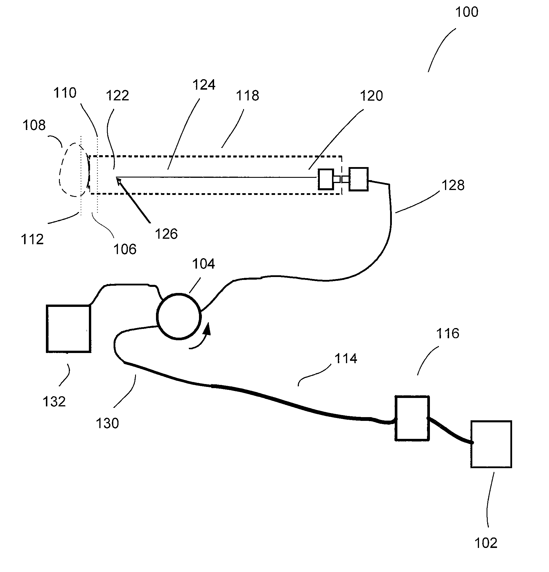
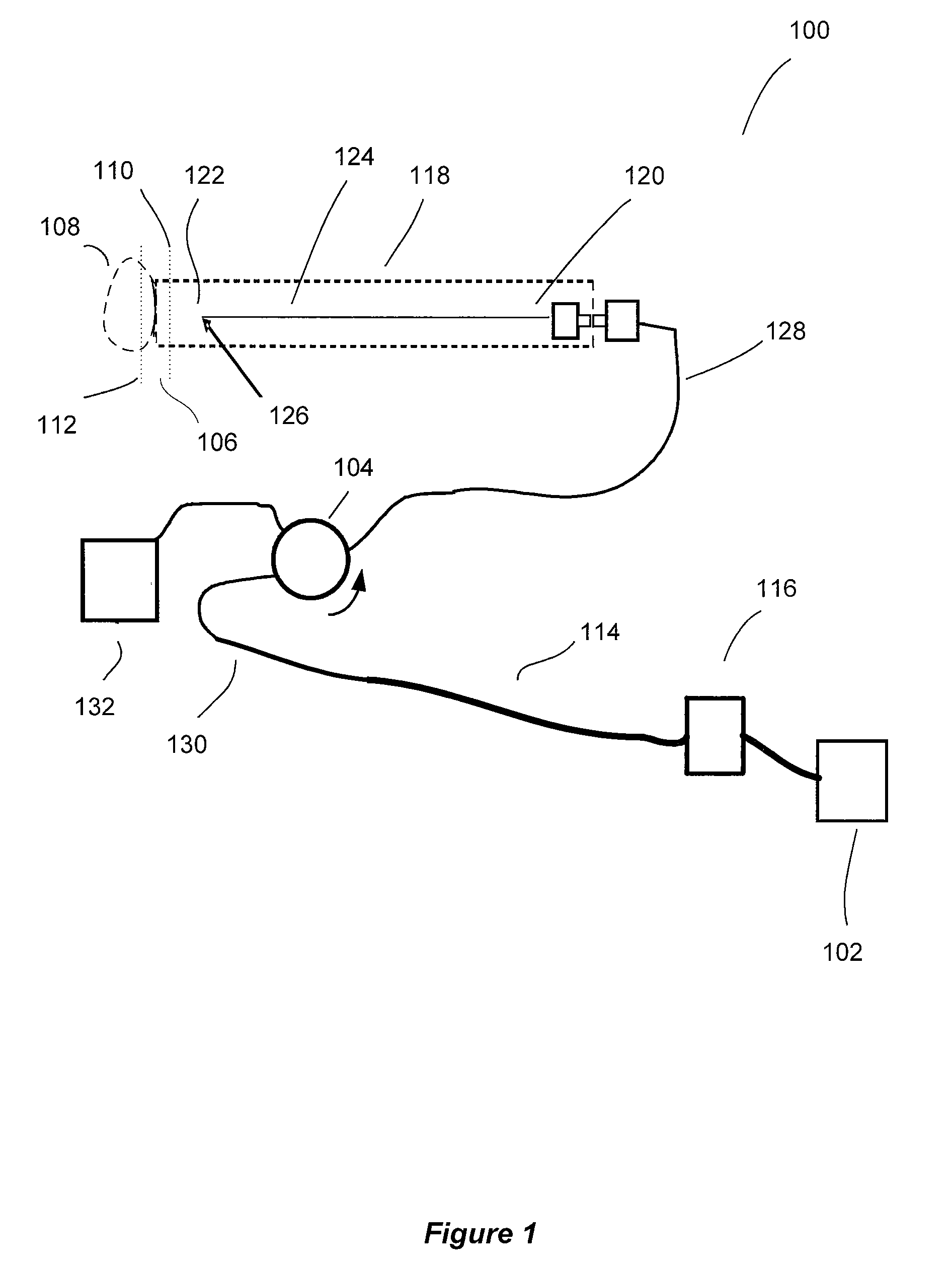
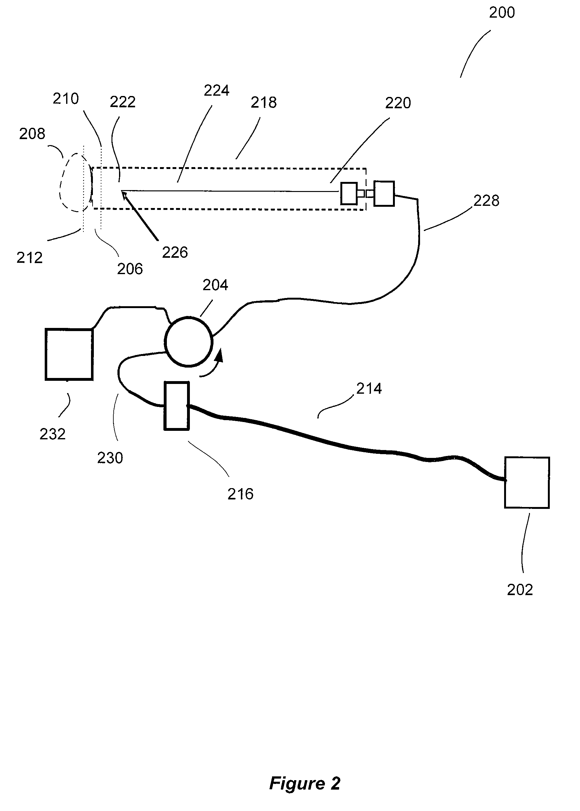
[0044]The subject application is directed to systems and methods for visualizing subsurface regions of samples, and more specifically, to a frequency domain optical coherence reflectometer and frequency domain optical coherence tomography device that provide internal depth profiles and depth images of samples. Modifications of the common path frequency domain optical coherence reflectometer are illustrated by means of examples of optical fiber devices being part of an apparatus for optical coherence tomography, although it is evident that they may be implemented with the use of bulk optic elements, and may be used as independent devices. The optical fiber implementation is preferable for use in medical applications, especially in endoscopy, where flexibility of the optical fiber provides convenient access to different tissues and organs, including internal organs via an endoscope.

[0045]Turning now to FIG. 1, there is shown a block diagram of an embodiment of the common path frequenc...


PUM


Abstract

Common path frequency domain optical coherence reflectometry / tomography devices include a portion of optical fiber with predetermined optical properties adapted for producing two eigen modes of the optical radiation propagating therethrough with a predetermined optical path length difference. The two replicas of the optical radiation outgoing from the portion of the optical fiber are then delivered to an associated sample by an optical fiber probe. The tip of the optical fiber serves as a reference reflector and also serves as a combining element that produces a combination optical radiation by combining an optical radiation returning from the associated sample with a reference optical radiation reflected from the reference reflector. The topology of the devices allows for registering a cross-polarized or a parallel-polarized component of the optical radiation reflected or backscattered from the associated sample. Having the optical path length difference for the two eigen modes of the optical radiation (which is an equivalent of an interferometer offset in previously known devices) differ from the reference offset in the devices of the present invention allows for relieving the requirements to the spectral resolution of the FD OCT engine and / or data acquisition and processing system, and substantially eliminates depth ambiguity problems.

Description

CROSS-REFERENCE TO RELATED APPLICATIONS[0001]This application is a continuation-in-part of U.S. patent application Ser. No. 11 / 456,414 which was filed on Jul. 10, 2006, which is based on and claims priority to provisional U.S. patent application Ser. No. 60 / 697,714, which was filed on Jul. 8, 2005.BACKGROUND OF THE INVENTION[0002]The present invention relates to systems and methods for visualizing subsurface regions of samples, and more specifically, to a frequency domain optical coherence reflectometer and frequency domain optical coherence tomography (OCT) device that provides internal depth profiles and depth resolved images of samples.[0003]Optical coherence reflectometry / tomography involves splitting an optical radiation into at least two portions, and directing one portion of the optical radiation toward a subject of investigation. The subject of investigation will be further referred to as a “sample”, whereas the portion of optical radiation directed toward the sample will be...

Claims


Application Information

Patent Timeline
Patent Type & Authority Patents(United States)
IPC IPC(8): G01B9/02G01B11/02
CPCG01N21/4795G01B9/02044G01B9/02057G01B9/02078G01B9/02065G01B9/02091G01B2290/70
Inventor FELDCHTEIN, FELIX I.GELIKONOV, GRIGORY V.
Owner IMALUX CORP
Why Eureka
Try Eureka