Magnetic nanomaterials and synthesis method

a technology of magnetic nanoparticles and nanoparticles, which is applied in the field of magnetic nanoparticles and magnetic nanoparticle synthesis methods, can solve the problems of high cost of synthesis, high permeability films only up to approximately 500 mhz, and inability to integrate them economically

Active Publication Date: 2008-09-30
NXP USA INC
View PDF3 Cites 5 Cited by
  • Summary
  • Abstract
  • Description
  • Claims
  • Application Information

AI Technical Summary

Benefits of technology

[0018]FIG. 1 shows a method 10 of preparing magnetic nanoparticles according to an embodiment of the invention. The method starts at 12 with a solution A at 14 that comprises a solvent, preferably an ether or an aromatic solvent such as toluene, anisole, dioctylether, or the like, that is added to a carboxylic acid, preferably Oleic acid, or the like. An amine, preferably Oleylamine or the like is then added to the solvent and Oleic acid solution to complete solution A. Of course, it will be appreciated that other solvents or amines not listed here may be used to perform the same decomposition. The next step 16 involves adding solution A to a metal-organic precursor such as a cobalt precursor Co(η3-C8H13)(η4-C8H12) to form solution B. It will be appreciated that other metal precursors may be used such as hydrocarbon metal complexes like Ni(η4-C8H12)2, and Fe(C9H7)2, or the like. It will also be appreciated that the components of solutions may be added and mixed together in any order to form solution B. At step 18, solution B is heated, for example by radiation at approximately 150° C. in anisole for approximately 48 hours, under pressure, for example 3 Bars of H2. In this embodiment, spherical monodisperse cobalt nanoparticles coalesce into nanorods of uniform shape over the process time at step 18, however, in this embodiment nanorods begin to appear in the solution after approximately 10 hours of reaction. The nanorods are crystalline hexagonal close packed (hcp), and grow along the c axis of the structure. The nanorods are in a thermodynamically stable form of cobalt after completion of the reaction which might take many hours. These thermodynamically stable cobalt nanorods will not rearrange into other forms such as spherical nanoparticles or any other form.

Problems solved by technology

However, current passive components, when integrated with active elements on integrated circuits consume large areas of silicon, making their integration often not economical.
However, at high frequency applications, for example high MHz or low GHz frequencies, methods such as this have performance limitations due to eddy current losses and loss-generating ferromagnetic resonance (FMR).
However, both methods produce high permeability films only up to approximately 500 MHz and generally cannot be thicker than 2-3 micrometers in order to minimise eddy current losses.
However, such performance is not sufficient for an effective magnetic field confinement needed to enhance passive devices.
The main drawback of this method comes from the destruction of the organic or inorganic matrix after the particle formation that yields by-products, which generally interfere with the nanoparticles.
However, due to their small size, the particles remain superparamagnetic at room temperature, and hence will not generate the required magnetic field confinement as achieved by high permeability materials.
However, similarly to above, the small size of the particles in the material makes them superparamagnetic, hence not useful for magnetic field confinement.
However this requires a high temperature process of, for example, approximately 300° C. Moreover, the nanorods obtained in this way are not thermodynamically stable and typically spontaneously rearrange into spherical nanoparticles within the first few seconds of the reaction.
Furthermore, these particles are superparamagnetic at room temperature and hence unsuitable for magnetic field confinement.

Method used


Image

  • Magnetic nanomaterials and synthesis method
  • Magnetic nanomaterials and synthesis method
  • Magnetic nanomaterials and synthesis method

Examples


Embodiment Construction

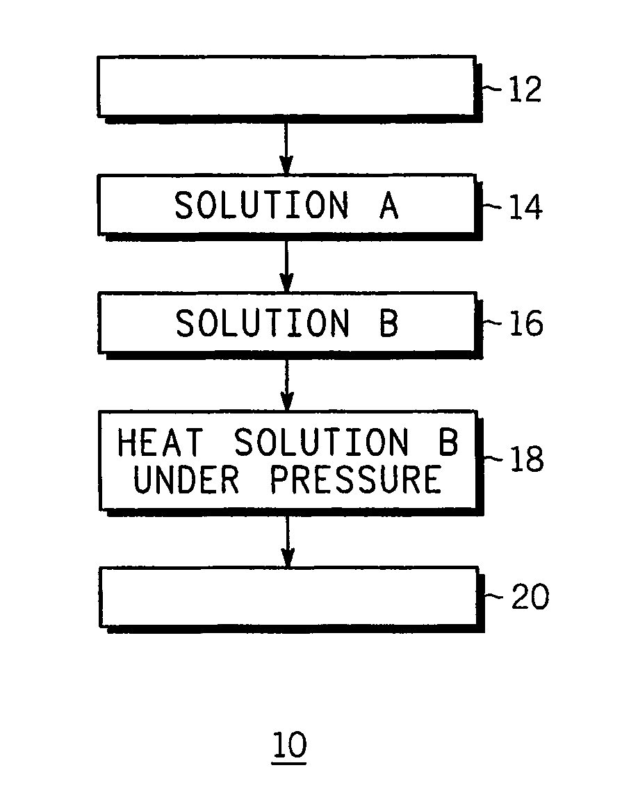
[0017]In high frequency integrated circuit applications, such as used in wireless portable electronic devices, passive components such as inductors and transformers, as well as structures for signal isolation, can be improved through the integration with magnetic nanoparticle materials. One particular method in accordance with an embodiment of the invention is the use of composite materials comprising of a matrix material containing a certain volume fraction of magnetic nanoparticles that have a saturation magnetization (Ms) and an anisotropy (Hk) where all three (volume fraction, Ms, and Hk) are optimised such that the composite material has a permeability high enough and a ferromagnetic resonance at high enough frequencies such as to allow improved RF-passive devices (such as inductors, transformers, isolation) at high MHz and GHz frequencies. Saturation magnetization (Ms) can be optimised through varying the chemical composition of the nanoparticles. Anisotropy (Hk) can be optimi...


PUM

PropertyMeasurementUnit
temperatureaaaaaaaaaa
temperaturesaaaaaaaaaa

Abstract

A magnetic nanoparticle (22), a magnetic nanomaterial (30), assembly (30), and a method for synthsising a magnetic nanoparticle, relating to thermodynamically stable and air stable ferromagnetic nanoparticles of adjustable aspect ratio made upon decomposition of organometallic precursors in solution in the presence of a reaction gas and a mixture of organic ligands. The magnetic nanomaterial comprises magnetic nanoparticles of homogeneous size, shape, and magnetic orientation that comprises a magnetic core (24, 34) ferromagnetic at room temperature and / or operating temperatures, and a non-magnetic matrix (26, 36) encapsulating the magnetic core. This magnetic nanomaterial could be used in high frequency integrated circuit applications, such as used in wireless portable electronic devices, to enchance magnetic field confinement and improve passive component performance at MHz and GHz frequency in a variety of passive and active devices, such as transformers, on-chip signal isolation, inductors, and the like.

Description

FIELD OF THE INVENTION[0001]The present invention relates generally to magnetic nanoparticles and method of synthesising magnetic nanoparticles. More specifically, the invention relates to ferromagnetic nanoparticles made upon decomposition of organometallic precursors, used for example in high density information storage media, light emitting diodes, passive components such as transformers, on-chip signal isolation, inductors, and the like, to improve passive component performance in high frequency integrated circuit applications.BACKGROUND OF THE INVENTION[0002]In high frequency integrated circuit applications, such as used in wireless portable electronic devices, there is a demand for miniaturisation, greater functionality, higher performance, and lower cost, which can be achieved through the integration of passive components such as inductors and transformers in integrated circuits. The lack of passive component integration on integrated circuits contributes to a passives-to-act...

Claims


Application Information

Patent Timeline
Patent Type & Authority Patents(United States)
IPC IPC(8): H01K1/00H01F1/24H01F1/00
CPCB82Y25/00H01F1/0045H01F1/0063H01F1/0072H01F1/0081Y10T428/2991Y10S977/81Y10S977/838Y10S977/83Y10T428/2998H01F1/00H01F1/047H01F1/06
Inventor RENAUD, PHILIPPEDUMESTRE, FREDERICCHAUDRET, BRUNOFROMEN, MARIE CLAIRECASANOVE, MARIE-JOSEZURCHER, PETERSTUMPF, ROLANDAMIENS, CATHERINE
Owner NXP USA INC
Why Eureka
Try Eureka