Miniaturized waste heat engine

a waste heat engine, miniaturized technology, applied in steam engine plants, machines/engines, mechanical equipment, etc., can solve the problems of high cost, high cost, and high cost, and achieve the effect of reducing engine pollution, improving overall engine efficiency, and improving engine performan

Inactive Publication Date: 2008-10-07
FILIPPONE CLAUDIO
View PDF29 Cites 19 Cited by
  • Summary
  • Abstract
  • Description
  • Claims
  • Application Information

AI Technical Summary

Benefits of technology

[0012]To summarize, the device of this invention recuperates a fraction of the energy normally lost in the form of heat from conventional power systems and combustion engines. By utilizing this energy to drive oxygen enhancing systems, engine pollution can be drastically reduced while engine performance is increased. By utilizing this same energy to drive a work-producing unit, the overall engine efficiency can be further improved since more power can be provided to the engine load. Then the overall engine power output is a result of the summation of the power normally provided by the engine and the power recuperated from the waste heat.

Problems solved by technology

This heat is normally lost through the exhaust gases and forced convection through the engine coolant system and radiator.
Such a low efficiency is normally not even considered for power generation; however, in this case the energy source is waste energy and recuperating even a small fraction of it only represents a gain for the overall engine efficiency.
Once water is injected inside the converter it expands instantaneously, changing its specific volume and making the heat transfer process extremely rapid.

Method used


Image

  • Miniaturized waste heat engine
  • Miniaturized waste heat engine
  • Miniaturized waste heat engine

Examples


Embodiment Construction

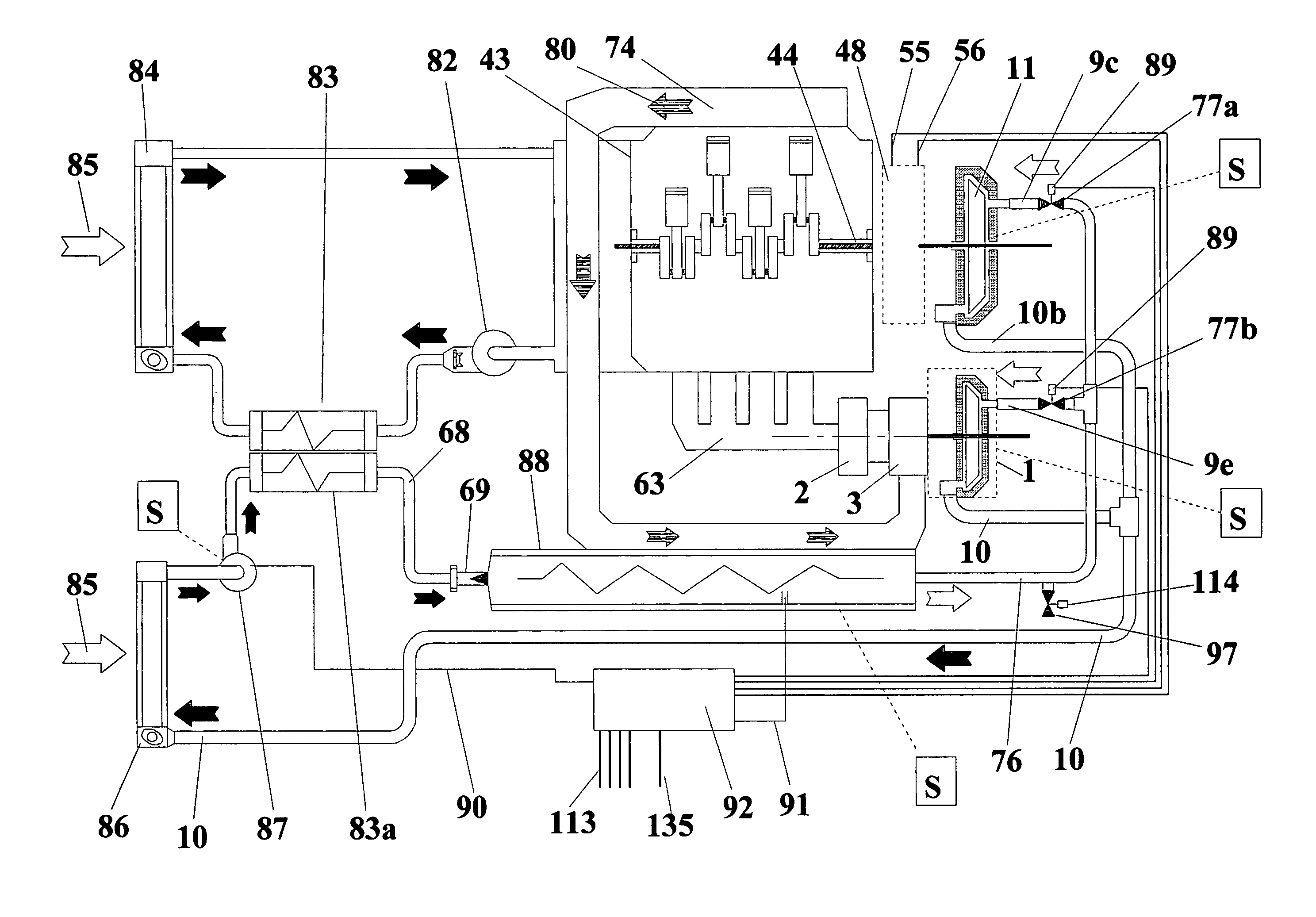
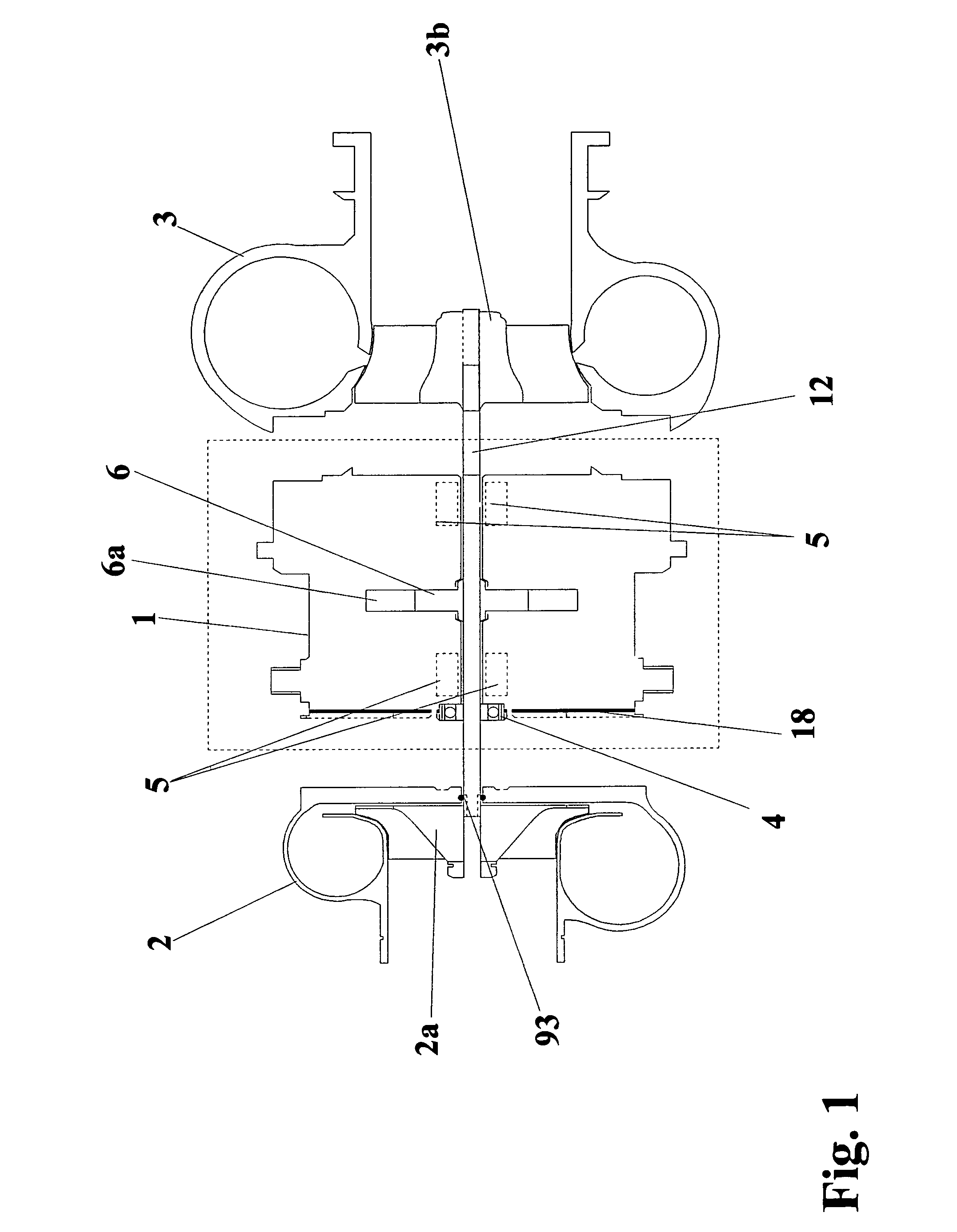
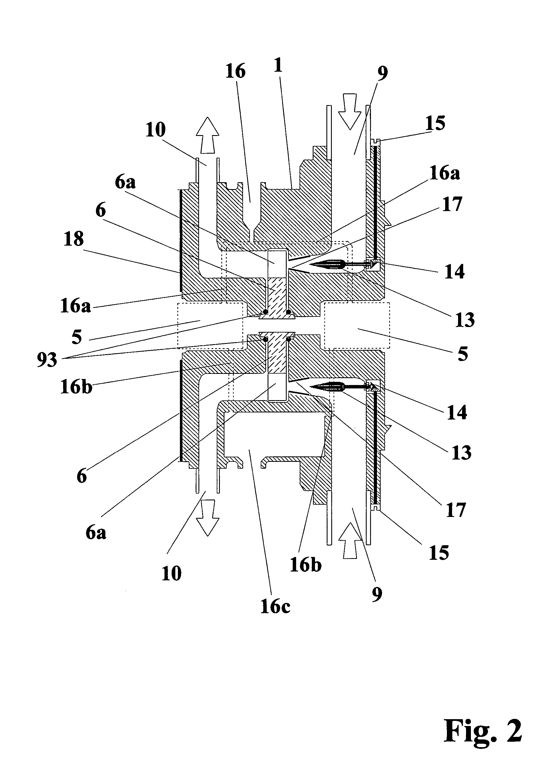
[0036]The working principles of the MWHE of the present invention are now described by utilizing the schematics and representations shown in FIG. 1-18.

[0037]The thermodynamic steps of the MWHE's cycle are represented in FIGS. 17, and 17A. Since the MWHE is formed by the combination of several sub-components, each of them characterized by unique features, the description of the MWHE should be somewhat simplified by describing the sub-components first. The most important sub-components of the MWHE cycle, expanders, converters, imploders, oxygenators and their applications are described in FIG. 1-16. FIGS. 17 and 17A, and basically provide the overall hydraulic connection and method of operation of each sub-component as part of a single device: the MWHE as a plant. Therefore, the basic components of a centrifugal compressor modified to integrate the vapor expander block of the MWHE are shown in FIG. 1. The body of the expander 1 is comprised inside the dashed block of FIG. 1. The vapor...


PUM


Abstract

A closed loop vapor cycle generated by a special device formed by heat transfer and a vapor expander it is utilized to convert waste heat from conventional power systems into additional thermodynamic work, thereby improving the overall power system efficiency. Superheated vapor (i.e. steam) is instantaneously produced inside special energy transfer apparatus where waste heat is converted into fluid energy with desired thermodynamic properties. The superheated vapor is then converted into mechanical energy through special work-producing units (expanders), thereby returning a significant fraction of the energy contained in the waste heat to the power system. When the power system under consideration is an internal combustion engine the energy contained in the exhaust gases (waste heat) is transferred back to the engine through one or more expanders directly or indirectly coupled with the engine load. The energy extracted from the waste heat can also be added back to the engine by an apparatus able to enhance the availability of oxygen (oxygenators) during the combustion. In this case, the engine also improves its dynamic response and reduces its production of toxic emissions. If the engine utilizes heavy fuels (i.e. diesel engines), this device completely eliminates the formation of the highly toxic particulate (black smoke), while significantly improving engine performance. The cost of the energy required to operate the device proposed in this invention is zero since it only recuperates and utilizes energy in the form of heat that is normally discharged into the environment.

Description

[0001]This is a continuation of Application No. 10 / 066,574, filed Feb. 6, 2002 now U.S. Pat. No. 6,729,137, which is a continuation of Application No. 09 / 582,233, filed Sep. 7, 2000, now U.S. Pat. No. 6,374,613, all of which are incorporated herein by reference.BACKGROUND OF THE INVENTION[0002]The present invention is characterized by a combination of vapor-to-mechanical energy converters driven by rapid heat transfer means able to instantaneously transfer energy from the products of combustion, or any heat source, to a thermodynamic fluid circulating inside an independent loop. This fluid moves inside the loop mainly as a result of its own expansion and transfers its energy to mechanical means through thermodynamic work-producing units or expanders. In this manner, the various components of this device constitute a special Miniaturized Waste Heat Engine (MWHE) able to recuperate and convert waste energy from combustion or heat sources into useful energy. By returning a significant ...

Claims


Application Information

Patent Timeline
Patent Type & Authority Patents(United States)
IPC IPC(8): F01K23/10F01K23/06F01N5/02F02B75/34F02G5/00
CPCF01K23/065F01N5/02F02B75/34F02G5/00F01N2240/02Y02T10/16Y02T10/166Y02T10/12
Inventor FILIPPONE, CLAUDIO
Owner FILIPPONE CLAUDIO
Why Eureka
Try Eureka