Hybrid deicing system and method of operation

a hybrid deicing and aircraft technology, applied in the direction of cleaning process and apparatus, chemistry apparatus and processes, cleaning using liquids, etc., can solve the problems of significant economic and waste management problems for airline and airport operators, lack of cleaning capacity to dislodge and remove ice from aircraft wings, and high cost and toxicity of glycol, etc., to reduce glycol usage and deicing cycle time, reduce the effect of ice removal and ice removal efficiency and effectiveness

Inactive Publication Date: 2008-10-07
PREMIER ENG & MFG
View PDF82 Cites 9 Cited by
  • Summary
  • Abstract
  • Description
  • Claims
  • Application Information

AI Technical Summary

Benefits of technology

[0013]This invention overcomes the disadvantage of the prior systems and provides a new hybrid deicing system that produces high velocity specially formed coaxial stream of Type I glycol or Type I glycol and water and air for efficiently and effectively removing ice from an aircraft. This invention (“hybrid deicing”), utilizing two fluid flow technologies and a unique coaxial nozzle, yields an efficient, stand-alone deicing system, i.e. a complete deicing system that reduces glycol usage and deicing cycle time. The new process consists of an inner high velocity stream of glycol surrounded by an outer stream of high velocity air. These two independent, coaxial streams work in concert to deuce the aircraft surfaces. Laboratory tests have validated that “hybrid deicing” can quickly and safely remove snow and ice frozen to a simulated aircraft surface. These tests indicate that deicing glycol usage can be reduced to 10% or less relative to conventional usage thereby providing the deicing operator with significant economic and waste management benefits. It is estimated hybrid deicing will reduce conventional deicing cycle time, in many deicing situations, by 10% or more providing an additional benefit to the operator. The specially formed stream includes a stream within a stream, wherein a deicing fluid such as glycol is entrained within and encased by a surrounding jacket of entraining fluid such air. Therefore the unique coaxial nozzle produces two essentially independent stream of Type I glycol fluid and air, both stream exiting the nozzle at high and substantially equal velocities in the range of 600-800 mph. The precise velocity of the streams depends on the upstream pressures and temperatures of the fluids.
[0014]This combination of high velocity coaxial stream within a stream of air and glycol hydrodynamically and thermally removes adhered ice, all types of freezing rain and snow. Further the surrounding sheath of forced air reduces the fluid energy and momentum loss of the inner deicing fluid and increases the effective snow / ice removal range (distance from the exit) of the combined streams.
[0015]This invention, utilizing high pressure glycol that is coaxially injected into a high velocity airstream, will de-ice aircraft as effectively as the conventional hot glycol wash method but with glycol application rates reduced to 10% or less of conventional rates. Consequently, this new deicing system significantly reduces conventional deicing costs and the impact on the environment.
[0016]This combination of high velocity coaxial stream within a stream of air and glycol hydrodynamically and thermally remove adhere ice, and light, wet and heavy snow.
[0017]This invention, utilizing high pressure glycol that is coaxially injected into a high velocity airstream and or stream within a stream high pressured injection, will de-ice aircraft as effectively as the conventional hot glycol wash method but with glycol application rates reduced to 10% or less of conventional rates. Consequently, this new deicing system significantly reduces conventional deicing costs and the impact on the environment.

Problems solved by technology

Such streams lack the cleaning capacity to dislodge and remove ice from aircraft wings.
However, glycol is expensive and toxic creating significant economic and waste management problems for airline and airport operators.
The life cycle cost of deicing glycol (i.e. Type I ethylene or propylene glycol) includes costs associated with its buying, storing, handling, heating, applying, collecting and reprocessing or disposal.
Various deicing systems using little or no glycol have been tried and to date these systems have demonstrated limited effectiveness.
Therefore, they have not gained acceptance by commercial deicing operators.
Accumulation of these winter products on aircraft surfaces (wings, tail and rudder) disturbs the aerodynamic performance of these-surfaces creating unstable flight conditions.
While conventional hot deicing fluid washdown of aircraft is very effective in removing these accumulations, glycol is expensive and toxic.
Furthermore, the deicing process takes time which causes flight delays during the winter months.
This combination of cost, waste management and flight delays creates a significant economic burden for the airlines during winter operations.
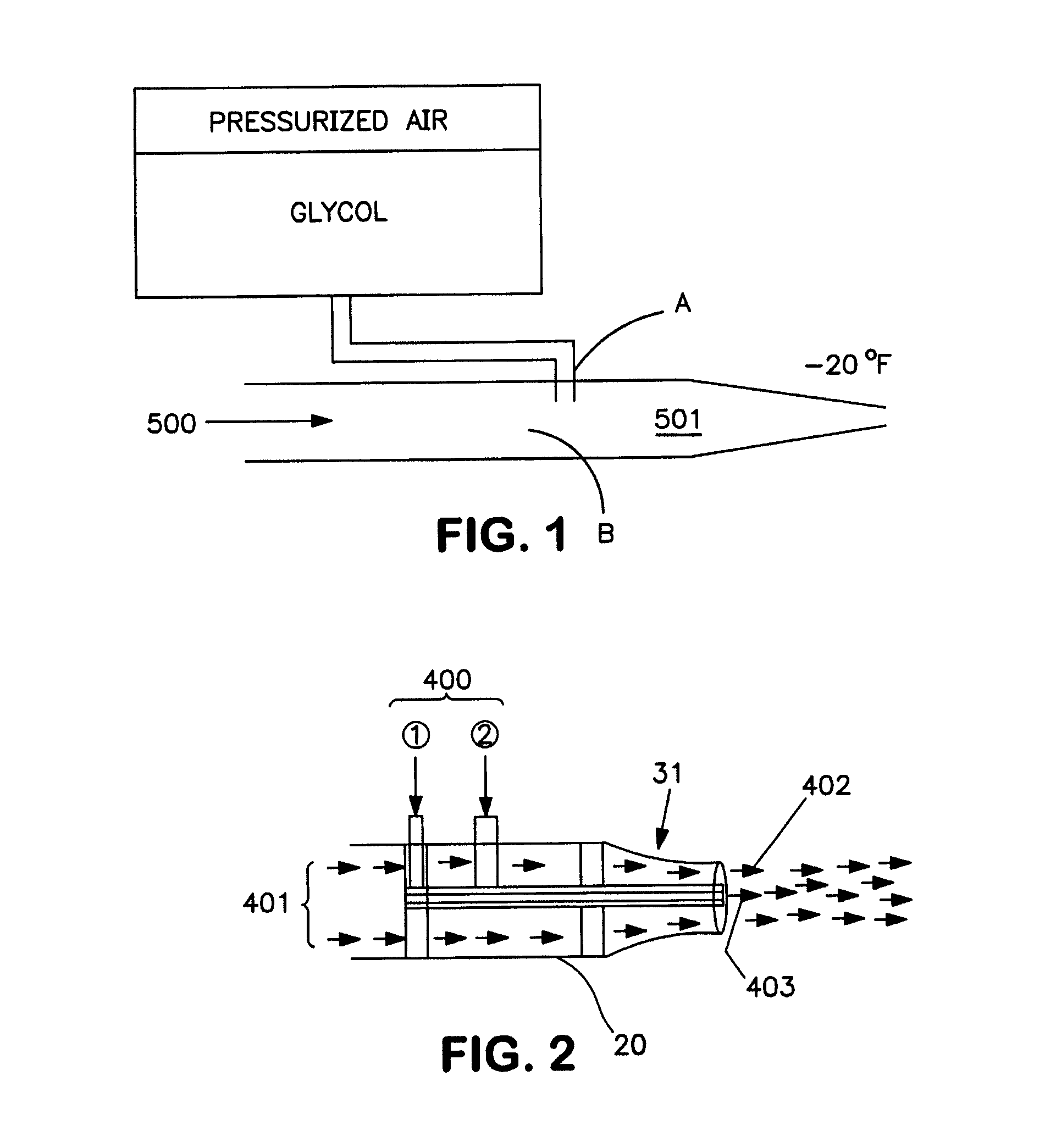
Various airline operators have indicated glycol injected at right angle to the primary axis of the airstream, as is shown in FIG. 1, reduces the effectiveness of forced air deicing.
The energy transfer process associated with the mixing and atomizing reduces the kinetic energy of the airstream which reduces the effectiveness of the air stream / glycol mixture to dislodge snow and ice that is frozen to or adhered to an aircraft.
Thus, this atomization process reduces the effectiveness of the airstream in breaking loose snow and ice that is frozen to or adhered to an aircraft surface and also reduces the effectiveness of the airstream in moving heavy, wet snow.
In addition, the mixture of atomized glycol and high velocity air adds more wetness to the snow further inhibiting the removal of wet snow.
Two fundamental problems have surfaced with this deicing process.
First, the frequency of the infra red heaters is such that snow melts slowly extending the deicing cycle time.
Second, testing to date shows that melting ice from the upper surfaces of the aircraft often re-freezes on the lower surfaces not exposed to the infra-red rays.

Method used


Image

  • Hybrid deicing system and method of operation
  • Hybrid deicing system and method of operation
  • Hybrid deicing system and method of operation

Examples


Embodiment Construction

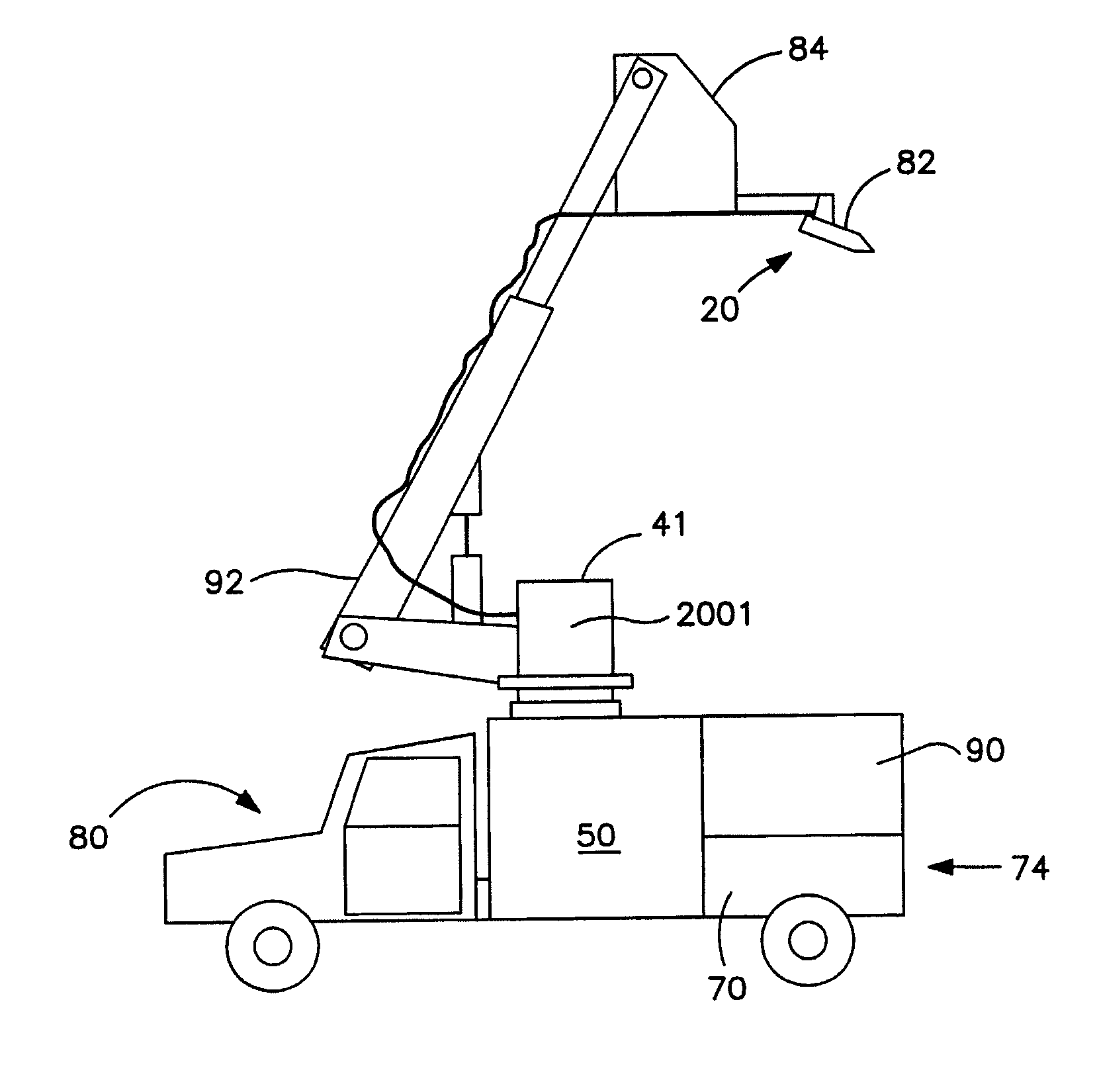
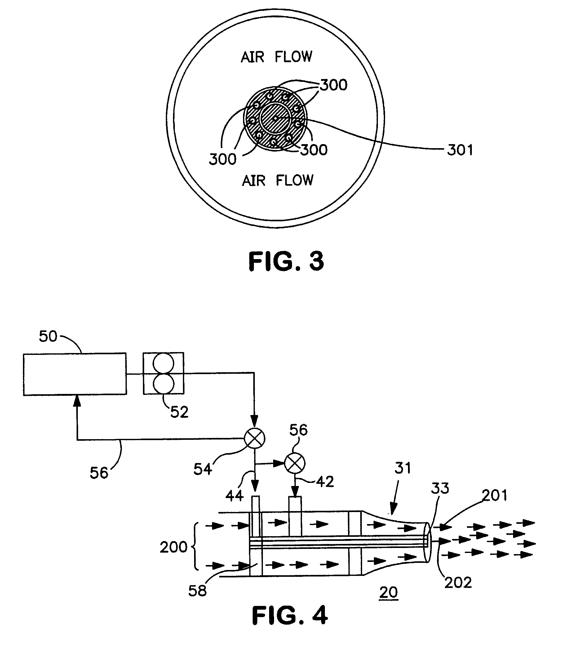
[0028]In FIG. 1, reference numeral 500 represents 400° F. air; 501 represents 50-200 mph. Referring now to FIG. 2, the new stand-alone ground based hybrid deicing system 10 of the present invention, (shown in detail in FIG. 7), utilizes a specially constructed coaxial nozzle assembly 20 that simultaneously delivers two independent, high velocity deicing streams. Preferably, a deicing fluid stream is encased within a high velocity airstream. The nozzle preferably has a special 0.060 inch diameter jetting orifice that produces a conical shaped jet. (in FIG. 2, reference numeral 400 represents heated deicing fluid from the triplex pump; 401 represents pressurized air from the centrifugal compressor (100 Lb per min); 402 represents 800 mph airstream; 403 represents 800 mph deicing fluid stream (high pressure / low flow mode); and 31 represents ASME “long radius” nozzle.)

[0029]The coaxial nozzle assembly 20 is specially designed to meld two fluid flow technologies, conversion of subsonic a...


PUM


Abstract

This invention overcome the disadvantage of the prior systems and produces a high velocity specially formed and constituted pressure aerodynamic stream for efficiently and effectively removing ice from an aircraft. The specially formed stream includes a stream within a stream, wherein a deicing fluid such a glycol is entrained within and encased by a surrounding jacket of entraining fluid such air. This deicing is now known as coaxial stream/stream within a stream deicing. The special nozzle allows the stream to maintain fluid separation over its flight path so that aircraft contact is made by to be known as coaxial stream/stream within a stream deicing. The coaxial stream/stream within a stream deicing is further enhanced by pressurizing the stream to deliver the stream as a high pressure high velocity stream to improved the aerodynamic sweeping action of the airstream.

Description

RELATED APPLICATION[0001]This application claims the benefit of and priority to earlier filed U.S. provisional application for a Glycol Air Deicing System Ser. No. 60 / 022,508 filed Jun. 17, 1996.FIELD OF INVENTION[0002]This invention is related to system for deicing aircraft and more particularly to a glycol / air coaxial stream deicing system wherein glycol and forced air are applied as a specially formed glycol stream within a forced air stream. The special stream is charged to hydronamically dislodge and remove ice or other frozen deposits from the aircraft.BACKGROUND[0003]Prior forced air deicing systems inject the glycol in an air stream air causing the glycol to atomized and dispersed in the air. Such streams lack the cleaning capacity to dislodge and remove ice from aircraft wings.[0004]Conventional aircraft deicing systems consist of ground or truck mounted spray systems which apply hot (180° F.) deicing fluid (a mixture of glycol and water) at rates up to 60 gpm to the aircra...

Claims


Application Information

Patent Timeline
Patent Type & Authority Patents(United States)
IPC IPC(8): B64D15/00B64F5/00
CPCB64F5/0054B64F5/0063B64F5/20B64F5/23
Inventor STANKO, JOHNPEARSON, LOWELL
Owner PREMIER ENG & MFG
Why Eureka
Try Eureka