End mill for orbital drilling of fiber reinforced plastic materials

a technology end mills, which is applied in the direction of shaping cutters, metal working devices, manufacturing tools, etc., can solve the problems of low inter-laminar strength and excellent in-plane strength of fiber reinforced plastic materials

Active Publication Date: 2008-10-07
KENNAMETAL INC
View PDF15 Cites 41 Cited by
  • Summary
  • Abstract
  • Description
  • Claims
  • Application Information

AI Technical Summary

Benefits of technology

[0004]Briefly, according to this invention, there is provided an end mill for orbital drilling of fiber reinforced plastics comprising a shank having a shank diameter; a neck having a neck diameter; and a cutting head having a cutting diameter, a corner radius, a dish angle and a back radius, wherein the neck diameter is about 65 percent to about 90 percent of the cutting diameter, the dish angle is between about 2 degrees to about 6 degrees, and the corner radius is between about 3 percent to about 8 percent of the cutting diameter.
[0005]In another embodiment, an end mill for orbital drilling of fiber reinforced plastics has a dish angle between about 2 degrees and about 6 degrees; a helix angle of between about 5 degrees and about 18 degrees; a radial rake angle between about 5 degrees and about 15 degrees; a gashing axial rake angle between about 3 degrees and about 10 degrees; and a primary clearance angle between about 10 degrees and about 18 degrees.

Problems solved by technology

FRP materials have excellent in-plane strength, but low inter-laminar strength.

Method used


Image

  • End mill for orbital drilling of fiber reinforced plastic materials
  • End mill for orbital drilling of fiber reinforced plastic materials
  • End mill for orbital drilling of fiber reinforced plastic materials

Examples


Embodiment Construction
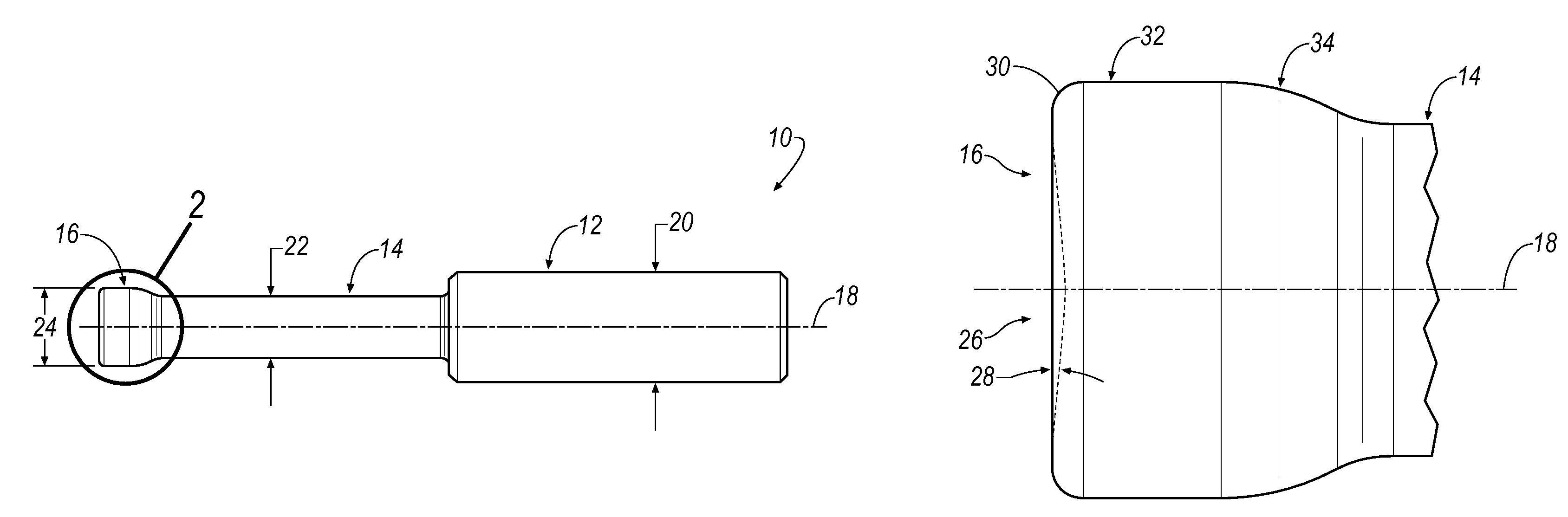
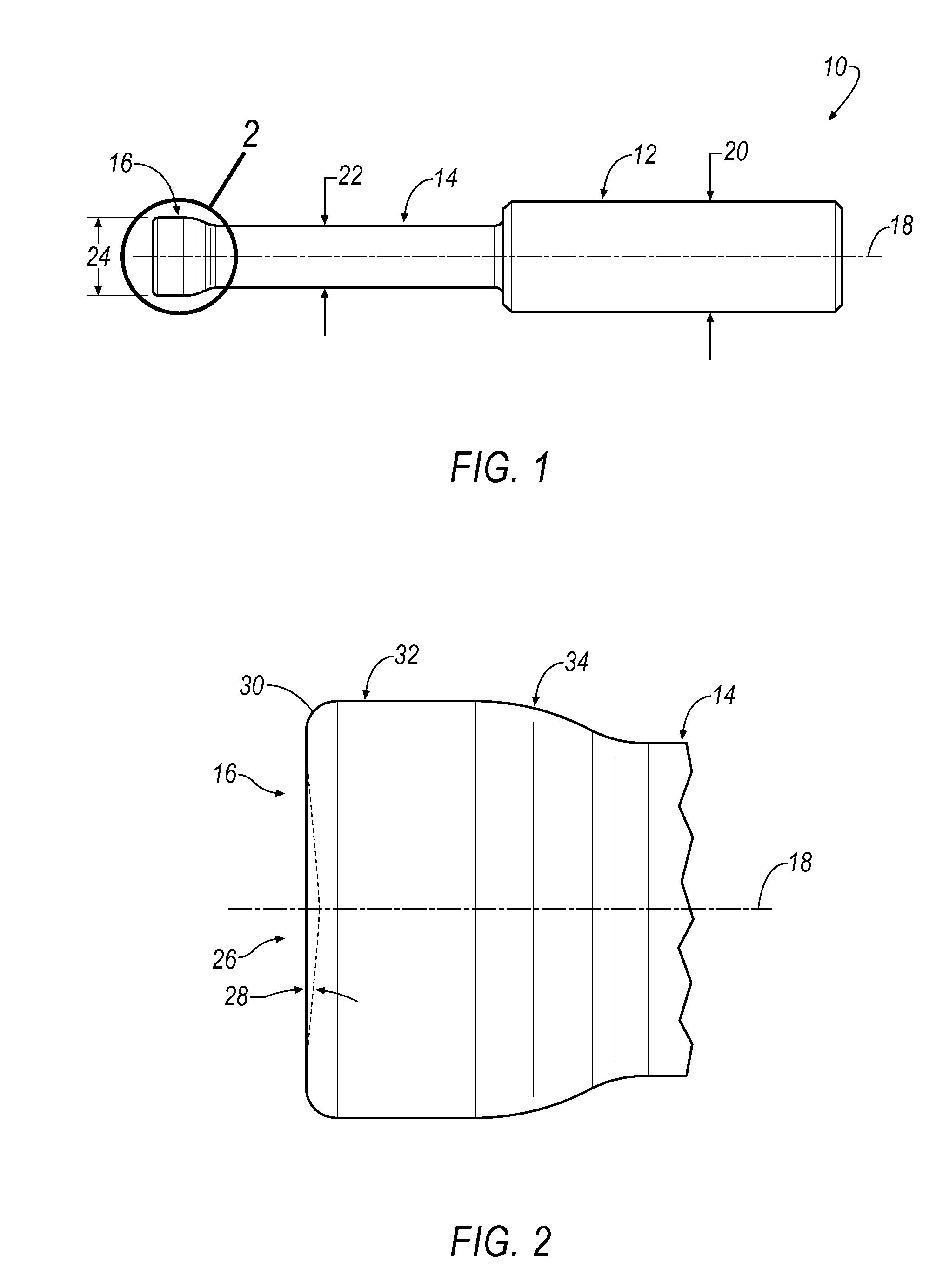
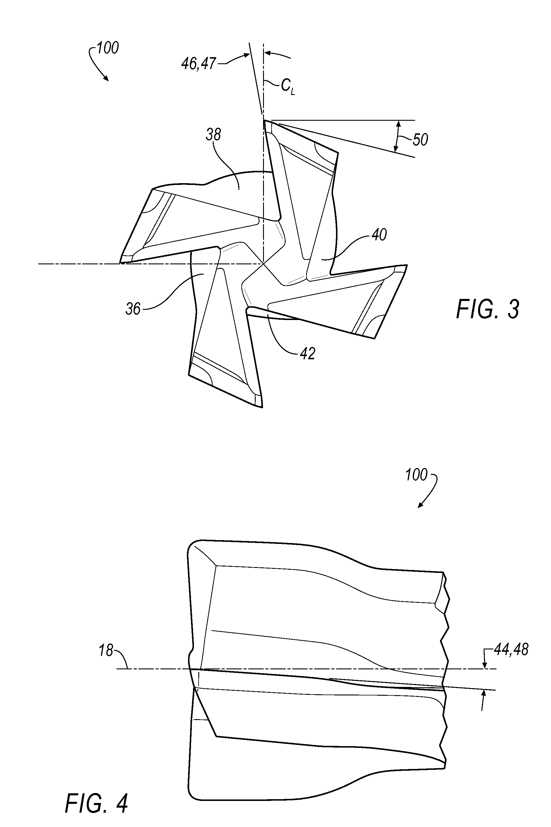
[0018]Tool Geometry

[0019]Referring to FIGS. 1 and 2, wherein like reference characters represent like elements, an end mill for orbital drilling of fiber reinforced plastics is generally shown at 10. In general, the end mill 10 includes has a shank 12, a neck 14, a cutting head 16, and a longitudinal axis 18. In one embodiment, the shank 12 has a shank diameter 20 of approximately 0.40 inches (10.16 mm), the neck 14 has a neck diameter 22 of approximately 0.22 inches (5.59 mm), and the cutting head 16 has a cutting diameter 24 of approximately 0.28 inches (7.11 mm). In general, the neck diameter 22 is less than the cutting diameter 24, for example, the neck diameter 22 can be approximately 65 to 90 percent of the cutting diameter 24.

[0020]As best seen in FIG. 2, the cutting head 16 includes a forward cutting end 26 that includes a dish angle 28 with respect to the end face. In one embodiment, the dish angle 28 can range from about 2 degrees to about 6 degrees. The cutting head 16 al...


PUM

PropertyMeasurementUnit
helix angleaaaaaaaaaa
radial rake angleaaaaaaaaaa

Abstract

A center or non-center cutting end mill for orbital drilling of fiber reinforced plastic (FRP) materials includes a shank, a neck, a cutting head and two or more flutes. The end mill has a tool geometry with the following features: a dish angle between about 2 degrees to about 6 degrees; a helix angle between about 5 degrees to about 18 degrees; an end teeth radial rake angle between about 0 degrees and about 15 degrees; a peripheral teeth radial rake angle between about 8 degrees and about 16 degrees; a gashing axial rake angle between about 3 degrees to about 10 degrees; and a primary clearance angle between about 10 degrees to about 18 degrees. The end mill is made from a tungsten carbide substrate with cemented cobalt in a range between about 3 to 10 wt. % and a diamond coating having a thickness in a range between about 8 to 20 μm.

Description

BACKGROUND OF THE INVENTION[0001]Fiber reinforced plastic (FRP) materials are widely used in aerospace industry due to its high specific strength and high specific stiffness. FRP materials are composite materials consisting of soft resin matrix and high strength fiber reinforcement. Typical fiber reinforcements include carbon fibers (CFRP), glass fibers (GFRP), Kevlar fibers, and the like. FRP materials are often processed into a laminated structure. FRP materials have excellent in-plane strength, but low inter-laminar strength. Fibers tend to delaminate during machining. FIG. 10 shows the fiber delamination around a machined hole using a conventional end mill.[0002]One approach to reduce the fiber delamination is to use an orbital drilling process. Orbital drilling is a holemaking operation by milling in which the center of an end mill orbits about the center of the intended hole while spinning on its own axis and moving in the axial direction. Orbital drilling is also called as ci...

Claims


Application Information

Patent Timeline
Patent Type & Authority Patents(United States)
IPC IPC(8): B23B5/10
CPCB23C5/10B23C2210/0407B23C2210/0485B23C2220/52B23C2222/28Y10T407/1948B23C2226/31B23C2228/10B23C2226/315Y10T407/1908Y10T407/1946B23C2226/27
Inventor NI, WANGYANGCHANDLER, JASON W.
Owner KENNAMETAL INC
Why Eureka
Try Eureka