Modular vertical floating pipe

a floating pipe and module technology, applied in waterborne vessel navigation aids, special-purpose vessels, machines/engines, etc., can solve the problems of inapplicability, otec plant idleness, polyethylene required, etc., and achieve the effect of simplifying the construction of otecwp and improving the ocean thermal energy conversion system

Inactive Publication Date: 2008-10-07
SAUCEDO EDUARDO +2
View PDF3 Cites 20 Cited by
  • Summary
  • Abstract
  • Description
  • Claims
  • Application Information

AI Technical Summary

Problems solved by technology

This approach is not applicable for an OTEC system for two reasons: (i) OTEC systems operate in much deeper waters, and; (ii) the high energy required to pump both surface and cold waters to the platform above sea level (some of the energy might be recovered by means of water turbines in the discharge).
There are four problems with the idea: (i) the flap valves are unlikely to resist the high pressure in deep waters (the pressure increases linearly with depth, and at the bottom portion of a 1,000 m CWP, the pressure will be 100 atms) and the chambers are likely to be filled with water; (ii) the fibers along the longitudinal axis would have to support the heavy weight of the pumping system and the weight of the pipe; (iii) construction and deployment of a single compliant pipe has complications not addressed in the patent, and; (iv) in the event of failure, the OTEC plant might be idle for months while a new pipe is constructed.
There are two main problems with the idea: (i) a 100 MW plant would require about 50 of such modules, and; (ii) given the number of modules and the thickness of the walls, the amount of polyethylene required will result in an expensive solution.
There are two problems with the idea: (i) the massive OTEC platform would have to be firmly anchored with tensioned legs above the column, prevented to move past the point of connection with the pivotable joint, and will be producing large stress on the pivotable joint by the continuous heave, roll and pitch produced by the waves, and; (ii) the thickness of the material to provide buoyancy and yet resist the pressures of deep water is not discussed in the patent.
Since concrete is not totally impermeable to high pressure water, this patent also has the problem of thickness of the concrete to prevent water entering the void spaces in deep water.
The main problem with this idea is the complicated assembly having to connect thousands of wires to provide the needed support of the modules hanging from the central tensile core.
Although maybe easier to repair than Daubin's idea, because of its retract-ability, it is a single unit and the pump at the bottom of the pipe is unnecessary.

Method used


Image

  • Modular vertical floating pipe
  • Modular vertical floating pipe
  • Modular vertical floating pipe

Examples


Embodiment Construction

[0064]The improvement of either one of the OTECWPs for an OTEC system, in the preferred embodiment, is illustrated in FIGS. 1 to 7.

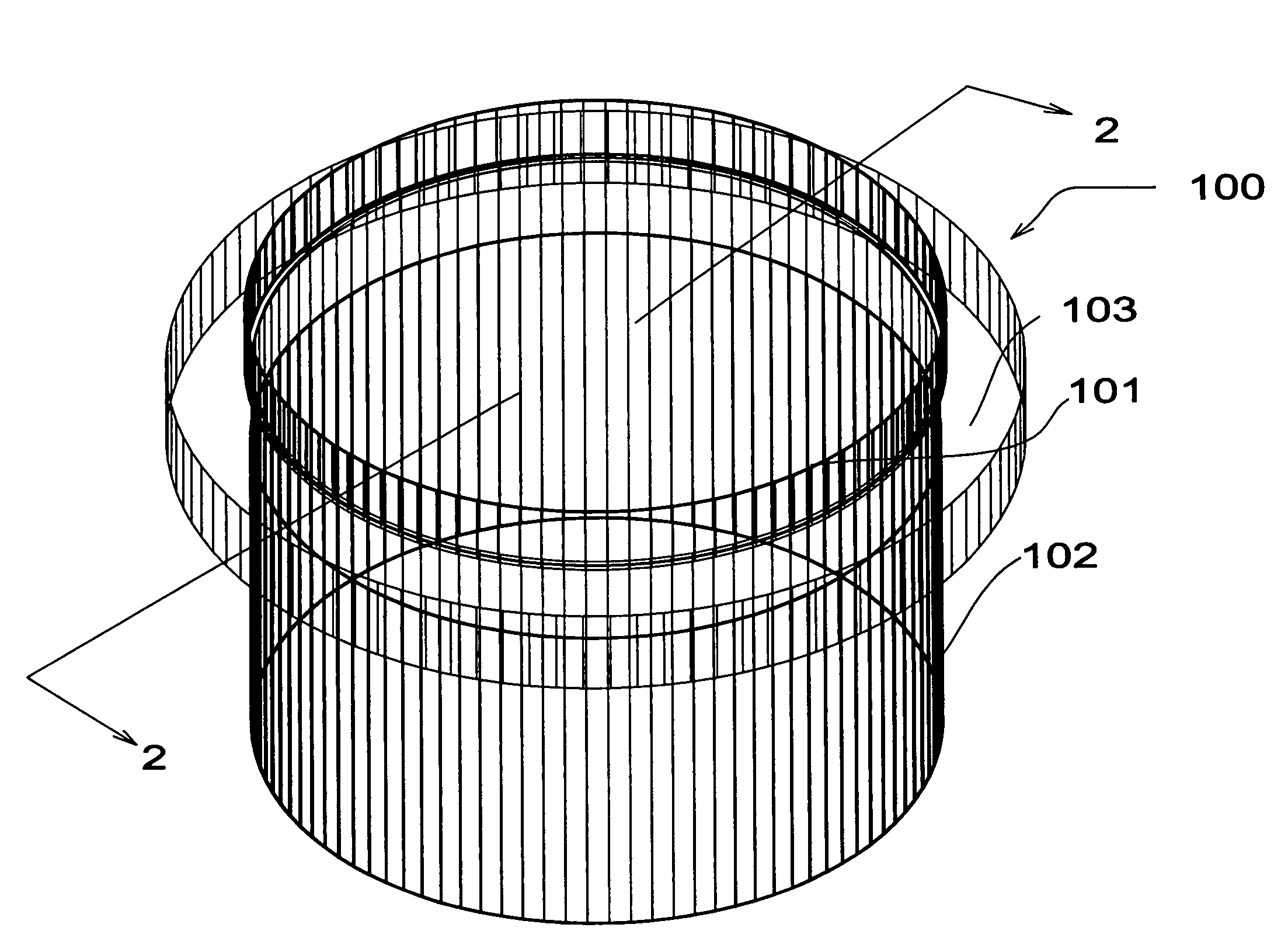
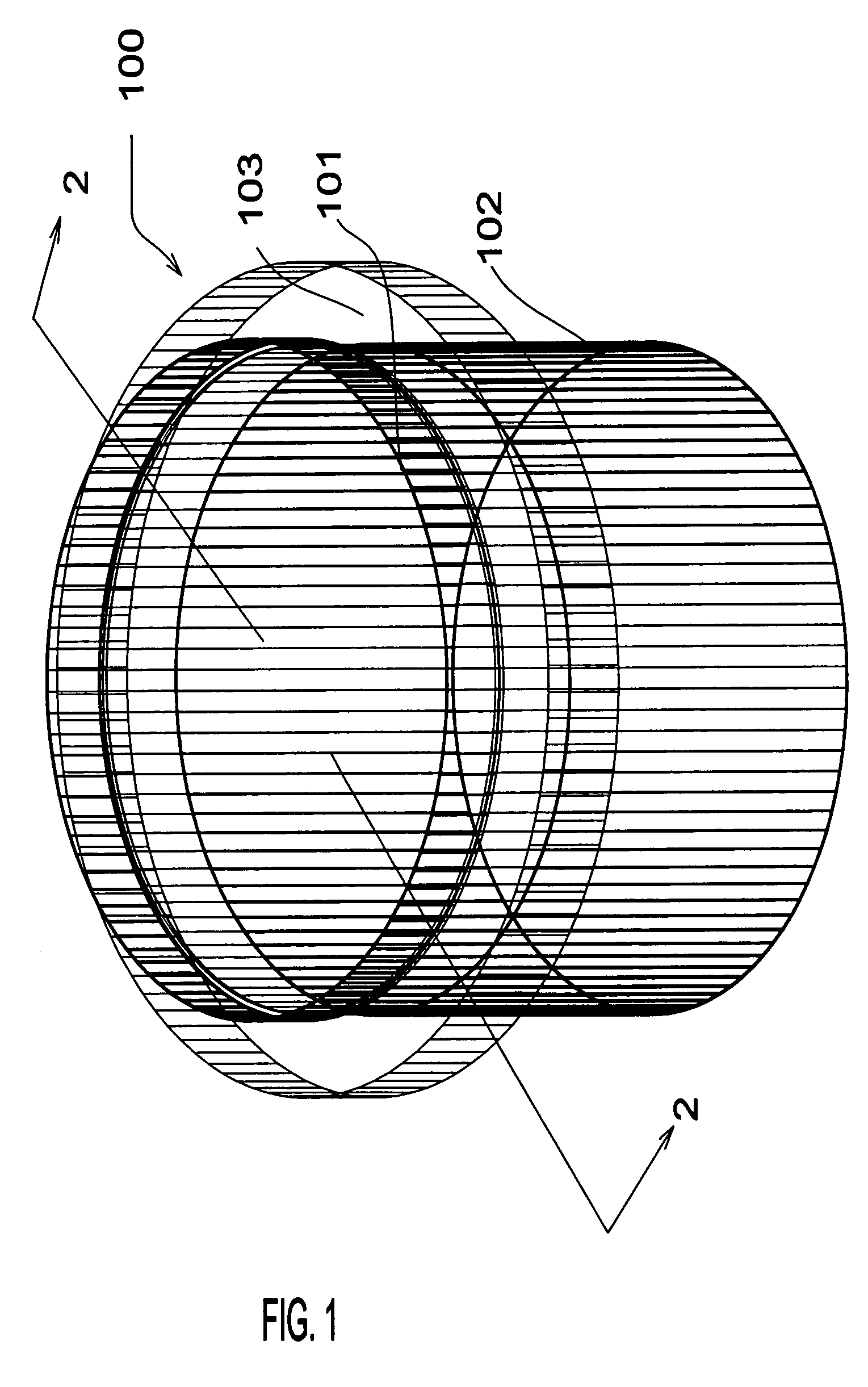
[0065]FIG. 1(a) shows an isometric view of a fully assembled module 100 of the preferred embodiment, assuming it is floating in the water, showing its three main parts: an upper pipe segment 101, a lower pipe segment 102, longer than the upper pipe segment and of a slightly smaller diameter, and an annular floater 103 of similar internal diameter as the outer diameter of the lower vertical pipe segment, restrained at that level by the collar (not shown) formed between the lower and upper pipe segments. Although the pipe segments are shown to be circular, they could be elliptic, oval or any other shape.

[0066]The OTECWP modular pipe segments could be constructed in a suitable dry dock in a ship yard, utilizing common construction techniques. The OTECWP modular pipe segments could be made out of concrete, steel or another suitable material that could be sha...


PUM


Abstract

Modular vertical floating pipe comprising a plurality of modules, each module formed by (a) two pipe segments of slightly different diameter, the lower segment with the smaller diameter segment joined by a collar with the upper pipe segment and (b) an annular floater of such dimensions that could slide up only in the lower vertical segment. A longer pipe would be formed by inserting one module on top of another, and repeating the operation until all modules have been utilized. The additional weight of a new module will be pushing the section of the pipe already formed down. The difference in diameter between the upper and lower segments will allow the pipe to bend with undersea currents. Appropriate seals will dampen the bending movements and cabling supporting a weight attached to cabling guides will prevent disengagement of the modules. By tying the cable to the top floater, the long pipe could be lowered and disconnected from the platform, allowing the platform and the pipe to ride a threatening storm independently.

Description

CROSS-REFERENCE TO RELATED APPLICATIONS[0001]On Oct. 15, 2004, I submitted a Provisional patent application (PPA), and received confirmation number 3933 for Application No. 60 / 618,607 which was mailed on Nov. 16, 2004. The following patent application refers to one of the inventions therein presented.FEDERALLY SPONSORED RESEARCH[0002]Not ApplicableSEQUENCE LISTING OR PROGRAM[0003]Not ApplicableBACKGROUND OF THE INVENTION[0004]The present invention relates to the Ocean Thermal Energy Conversion (“OTEC”) system and more particularly to the Cold Water Pipe (“CWP”) for such system. Since the present invention is also applicable to the Surface Water Pipe (“SWP”) and the Discharge Water Pipe (“DWP”), if needed for the system, the three pipes will be herein called individually the Ocean Thermal Energy Conversion Water Pipe (“OTECWP”) or, if reference is made to more than one, as Ocean Thermal Energy Conversion Water Pipes (“OTECWPs”). OTEC systems are energy (and fresh water) producing sys...

Claims


Application Information

Patent Timeline
Patent Type & Authority Patents(United States)
IPC IPC(8): B63B22/00
CPCB63B38/00F16L9/22F16L11/133B63B2035/4466Y02E10/34F03G7/05F16L1/15B63B35/00Y02E10/30
Inventor SAUCEDO, EDUARDOSAUCEDO, RAÚL AGUSTINBARNES, FRANCISCO JOSE
Owner SAUCEDO EDUARDO
Why Eureka
Try Eureka