Antenna device with ion-implanted resonant pattern

a technology of ion-implanted resonance and antenna device, which is applied in the direction of resonant antenna, individually energised antenna array, protective material radiating elements, etc., can solve the problems of increasing costs, and achieve the effects of enhancing the antenna gain, reducing noise, and improving wireless technology quality

Inactive Publication Date: 2008-10-07
MITAC TECH CORP
View PDF8 Cites 2 Cited by
  • Summary
  • Abstract
  • Description
  • Claims
  • Application Information

AI Technical Summary

Benefits of technology

[0009]In comparison with the conventional technologies, which the resonant patterns are in fact individually manufactured and then arranged on a base or an inner surface in the electronic devices, the present invention implants an resonant pattern inside the structure of an electronic device by applying the process of Ion-implantation. Besides, the electronic device co-structured and ion-implanted resonant pattern magnifies the electrical current fed to and transceived by the antenna, as well as reduces the noise and enhances the gain of the antenna to upgrade the quality of the wireless technology. Further, the present invention can be adapted into a wide range of electronic devices when used in different fields of application.

Problems solved by technology

Such manufacturing is not only troublesome bust also increases costs.

Method used


Image

  • Antenna device with ion-implanted resonant pattern
  • Antenna device with ion-implanted resonant pattern
  • Antenna device with ion-implanted resonant pattern

Examples


Embodiment Construction

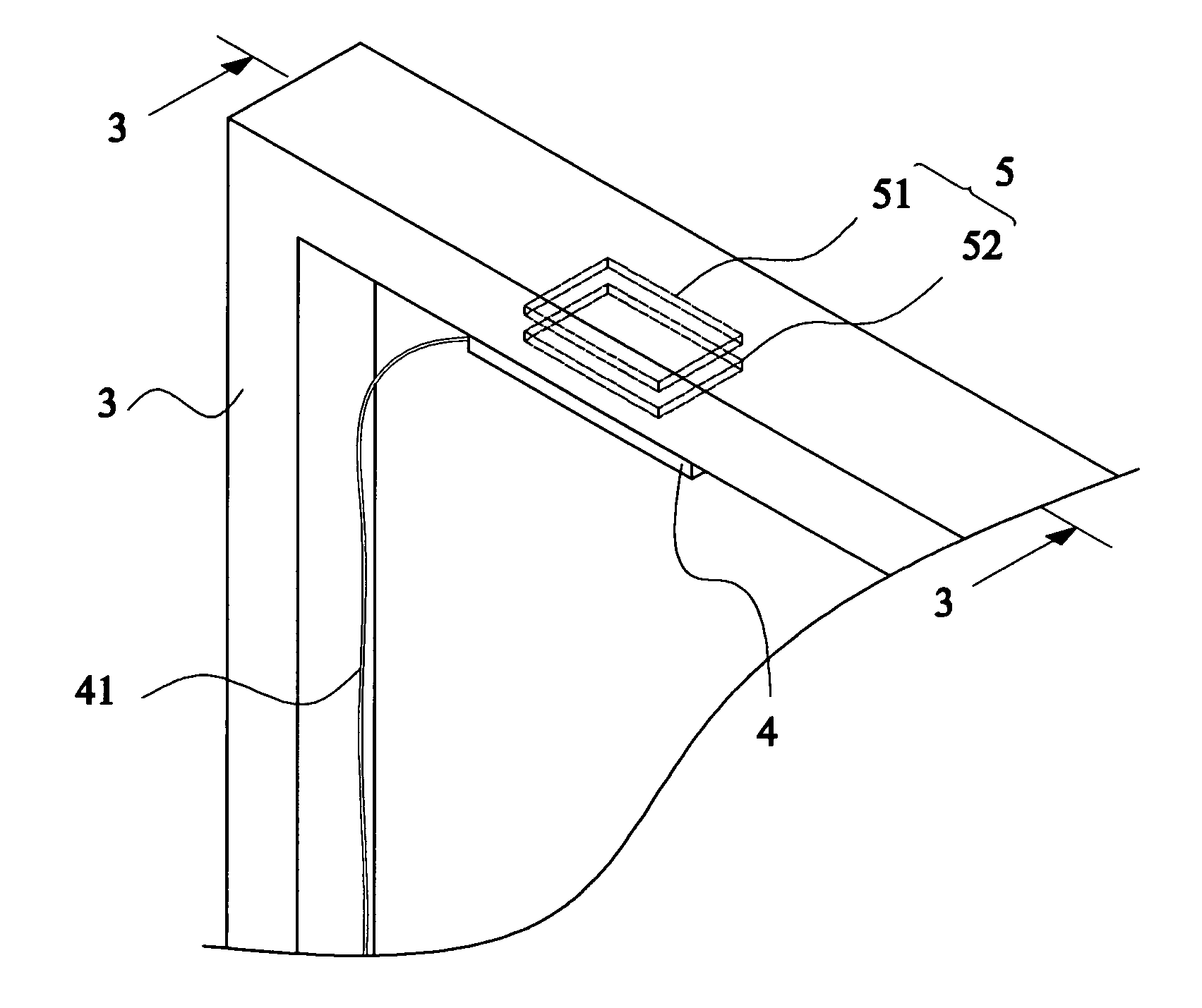
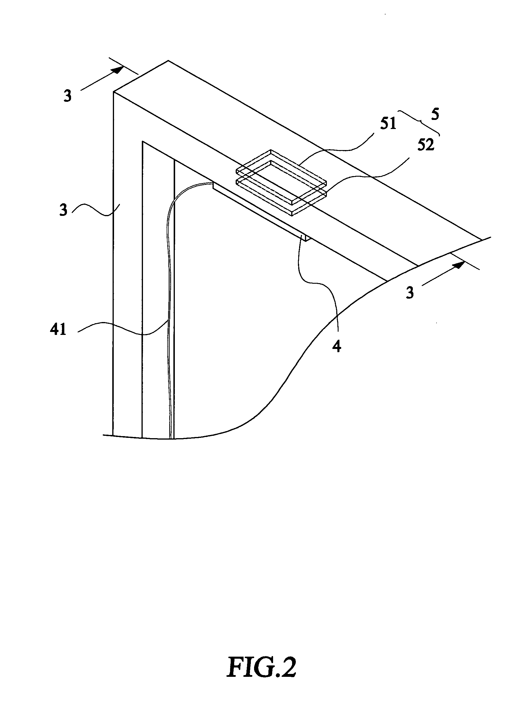
[0015]With reference to the drawings FIGS. 2 and 3 that is an assembled perspective view of an antenna device with an ion-implanted resonant pattern in accordance with the preferred embodiment of the present invention and a sectional view taken along line 3-3 of FIG. 2, a substrate 3 of an electronic device (not shown in the figure) includes an antenna element 4, which is electrically connected to an antenna module (also not shown in the figure) of the electronic device by an antenna signal feeding line 41, for transceiving a wireless signal of a predetermined radiation frequency.

[0016]In the preferred embodiment of the present invention, the substrate 3 could be a casing of the electronic device, and the material of the substrate 3 could be either air, metal, or plastic in accordance with the different fields of application of the antenna element 4. Further, the connection between the antenna element 4 and the antenna signal feeding line 41 could be either direct wire connection, c...


PUM


Abstract

Disclosed is an antenna device having a substrate, an antenna element for transceiving a wireless signal, an antenna signal feeding line for feeding the wireless signal, and an ion-implanted resonant pattern, which includes a first coupling pattern implanted in the substrate by an Ion-implantation process and a second coupling pattern formed at a position corresponding to the first coupling pattern with a predetermined distance therebetween, formed at an adjacent position with respect to the antenna element. As the antenna element transceives the wireless signal of the predetermined radiation frequency and generates an induction voltage, the first coupling pattern and the second coupling pattern each generates a coupled induction voltage and a capacitance therebetween, hence forming a resonance with the antenna element.

Description

FIELD OF THE INVENTION[0001]The present invention relates to an antenna device with a resonant pattern, and in particular to an antenna device with an ion-implanted resonant pattern.BACKGROUND OF THE INVENTION[0002]It is well known that an antenna is the key element to transmit / receive (transceive) microwaves in wireless technology such as wireless communication and wireless data transfer, where the antenna converts electrical currents generated by a transmitter into microwaves and transmits the microwaves in free space. The antenna also captures microwaves and converts them into electrical currents, which are then processed by a receiver. As a result, the characteristics of the antenna deeply affect that of the wireless technology, and the antenna can be referred as the index to examine the quality of the wireless technology.[0003]Currently, antennas of conventional use are required with specific dimensions, and only the antennas with the required dimension optimize the feeding and...

Claims


Application Information

Patent Timeline
Patent Type & Authority Patents(United States)
IPC IPC(8): H01Q1/38H01Q21/00
CPCH01Q1/2266H01Q1/38H01Q1/40
Inventor CHENG, YU-CHIANGCHANG, PING-CHENGCHOU, CHENG-ZING
Owner MITAC TECH CORP
Why Eureka
Try Eureka