
System architecture for linking channel banks of a data communication system

a data communication system and system architecture technology, applied in the field of telecommunication systems and subsystems, can solve the problems of limited network card extension approach, bulky and expensive bus extension cables, and limited noise coupling as to the number of channel banks

Active Publication Date: 2008-10-07
ADTRAN
View PDF2 Cites 25 Cited by
  • Summary
  • Abstract
  • Description
  • Claims
  • Application Information

AI Technical Summary

Benefits of technology

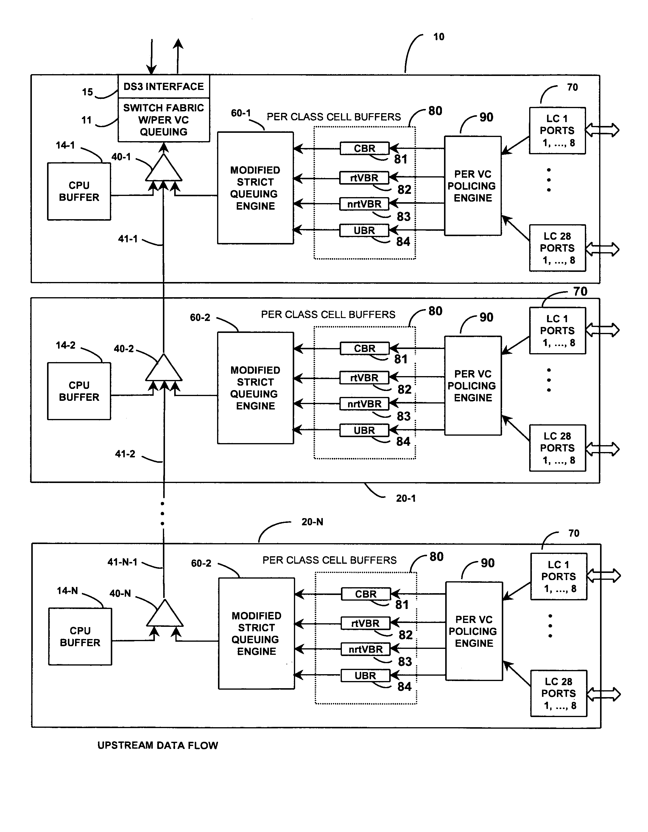
[0018]The subtraction unit is coupled to selectively receive from the scheduler controller a prescribed value C corresponding to that count value of the register that equates exactly to one cell. The scheduler controller monitors the contents of its associated cell buffer within the switch fabric, as well as the contents of the register, and generates a ‘transfer cell’ output, in response to the cell buffer containing a complete ATM cell, and in response to the contents of the accumulator register being greater than the summation of successive ones of the value M that corresponds to a complete ATM cell. When generating this transfer cell output, the scheduler controller causes the subtraction unit to subtract the value C from the summation output produced by the adder, thereby reducing the contents of the accumulator register by a count value that corresponds to one complete ATM cell.
[0024]Pursuant to the methodology disclosed in the '102 application, the master shelf assigns each expansion channel bank a shelf identifier code, which is included as part of the header of any information packet between the master shelf and an expansion channel bank. Whenever a message is transmitted downstream from the master, a respective expansion channel bank will compare the shelf ID code it has previously been assigned by the master with the shelf ID field in the packet. If the two IDs match, the shelf captures the packet. In addition, irrespective of whether a shelf's ID code matches the shelf ID field of the packet, if the shelf address field of the packet has a value of one, the expansion shelf will capture the packet. The shelf address field enables the master to keep track of changes to the participation of expansion shelves within the overall system.
[0026]As a packet is forwarded from the master downstream among the expansion shelves in a daisy chain manner, each expansion channel bank will compare its shelf ID code with the shelf ID field in the packet. If the two IDs match, the shelf captures the packet. In addition, irrespective of whether a shelf's ID code matches the shelf ID field of the packet, if the shelf address field of the packet has a value of one, the shelf will capture the packet. The address field and the shelf ID enable the master to keep track of changes to participation of expansion shelves within the system.
[0034]Because the DSLAM system is formed of a master shelf containing a master channel bank and some number of expansion shelves containing expansion channel banks that are connected together in a daisy chain manner, the possibility of a shelf becoming disconnected and then reconnected into a different order in the daisy chain sequence is relatively high. The use of a variable shelf address field and a fixed shelf ID field in the packet header enables the master shelf to determine if and where an expansion shelf has been moved. In fact, the communication and address protocol methodology of the invention allows all the shelves to be disconnected and shuffled to new locations; the master shelf is still able to keep up with their new locations through their shelf ID codes. When a replacement shelf is reinserted into the location of a remove shelf, which may be its own or another, the newly inserted shelf will go through the shelf initialization routine described above, allowing the master to adjust back to the old shelf locations. The master shelf retains an expansion shelf's location in EEPROM, so that after a power cycle, the master will be able to promptly reconstruct a shuffled stack of expansion shelves with their corresponding shelf IDs.

Problems solved by technology

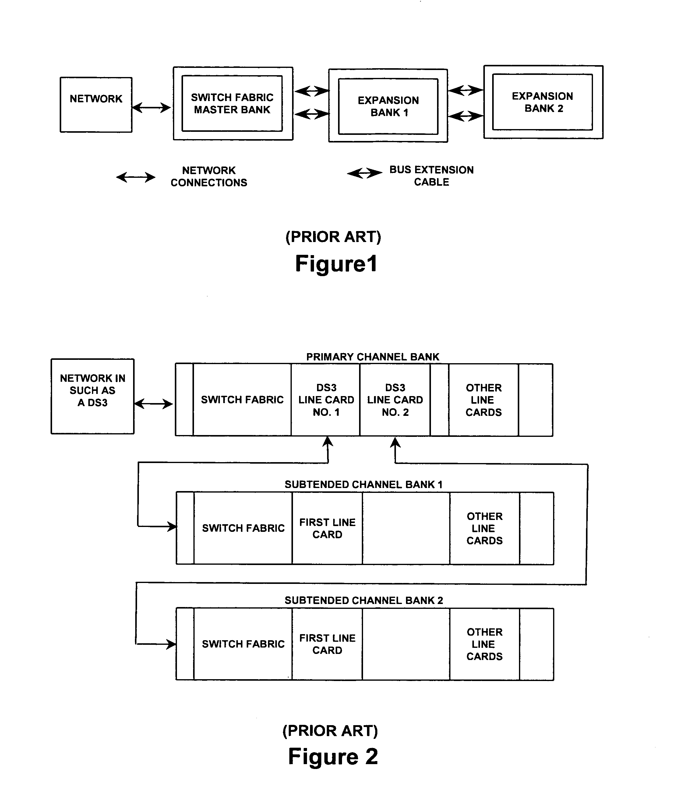
Given the fact that the extension bus is shared among the master channel bank and one or more expansion channel banks, a problem may arise if one of the channel bank cards malfunctions and seizes control of the extension bus.
Moreover, since the channel banks are connected by way of a bus extension cable, there is a practical, noise-coupling limitation as to the number of channel banks that can be daisy chained together.
In addition, the bus extension cable is usually bulky and expensive.
The second, network card extension approach is also limited by a number of factors.
A first is the fact that since the channel banks are interlinked by using network connections that usurp multiple line card slots, the primary bank loses the availability of line cards that would otherwise be used to provide service to customers.
Also, the use of network cards adds a greater expense for data expansion, and limits the number of customers that can be serviced by the host channel bank.
In addition, as each of the subtended channel banks requires a network connection, the switch fabric must be replicated on each subtended channel bank, which adds to the expense.

Method used


Image

  • System architecture for linking channel banks of a data communication system
  • System architecture for linking channel banks of a data communication system
  • System architecture for linking channel banks of a data communication system

Examples


Embodiment Construction

[0054]Before detailing the single switch-fabric based, multi-channel bank architecture in accordance with the present invention, it should be observed that the invention resides primarily in a prescribed arrangement of conventional digital communication circuits and components and attendant supervisory communications microprocessor circuitry, as well as application software therefor, that controls the operations of such circuits and components. In a practical implementation that facilitates its incorporation into commercially available digital telecommunication transceiver equipment, the inventive arrangement is preferably implemented using field programmable gate array (FPGA)-configured and application specific integrated circuit (ASIC) chip sets. In a hardware implementation of such chip sets, digital ASICs are preferred.

[0055]Consequently, the configuration of such subsystems and components and the manner in which they may be interfaced with both serial and parallel telecommunica...


PUM


Abstract

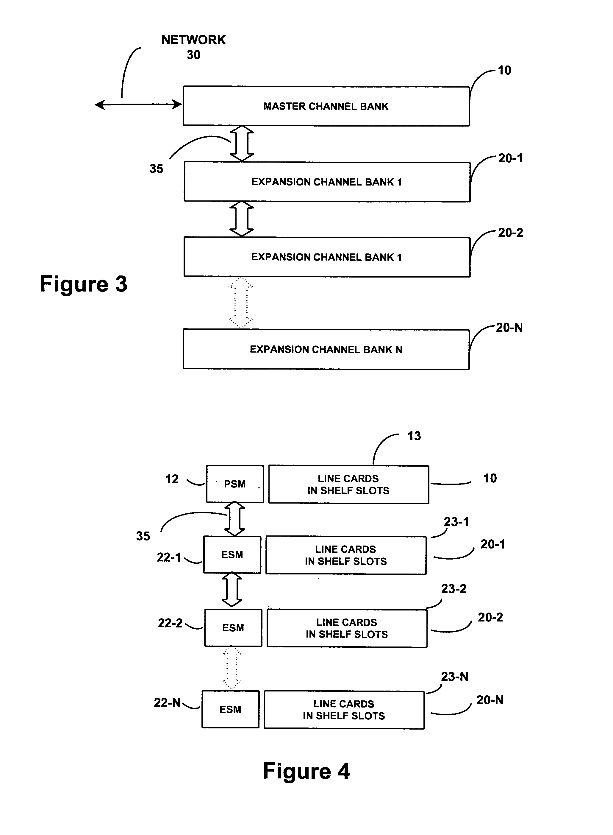
A single switch fabric-based, multi-channel bank digital subscriber line access multiplexer includes a master channel bank containing a master switch module in which the switch fabric and a downstream-directed traffic scheduler reside, and one or more expansion channel banks that are linked with the master channel bank by way of upstream and downstream communication links. Distributed among the channel banks are respective policing mechanisms and cell rate control mechanisms that control upstream-directed communications from line card ports of each expansion channel bank to the switch fabric. Downstream data transmissions are locked to network timing, and are scheduled by a centralized scheduling mechanism resident in the master channel bank.

Description

FIELD OF THE INVENTION[0001]The present invention relates in general to telecommunication systems and subsystems thereof, and is particularly directed to a multi-channel bank digital subscriber line access multiplexer (DSLAM) architecture, having a master channel bank through which a single connection to the network is provided, and one or more auxiliary or expansion equipment shelves / channel banks, that are coupled with the master channel bank by way of a Gigabit Ethernet communication link, without having to expropriate line card slots of the master channel bank for inter-channel bank connections.BACKGROUND OF THE INVENTION[0002]An on-going objective of the telecommunications industry is to increase the number of customers that may be serviced by a single channel bank connection with a network, such as but not limited to a DS3 or OC3 network connection. To date, this objective has been addressed primarily by using one of two approaches: 1—bus extension; and 2—channel bank subtendi...

Claims


Application Information

Patent Timeline
Patent Type & Authority Patents(United States)
IPC IPC(8): H04J3/16
CPCH04L12/5601H04L49/45H04L2012/5606H04L2012/5614H04L2012/5658H04L2012/5679
Inventor BURCH, RICHARD A.JENSEN, NEIL M.MCMAHAN, DENNIS B.ROCHELL, TIMOTHY DAVIDTOTH, ROBERT JAMES
Owner ADTRAN
Learn More