Supercharge Your Innovation With Domain-Expert AI Agents!

Fixing member, fixing device and image forming device with metal layers having different specific resistances

a technology of fixing device and fixing member, which is applied in the direction of electrographic process apparatus, instruments, optics, etc., can solve the problems of increasing power consumption, not meeting the recent demand for energy-efficient machines, and wasting time on heating the surface of the roll to be heated, so as to improve the efficiency of the heating process and reduce the cost of operation. , the effect of preventing damage to the pressure applying member

Active Publication Date: 2008-10-07
FUJIFILM BUSINESS INNOVATION CORP
View PDF7 Cites 8 Cited by
  • Summary
  • Abstract
  • Description
  • Claims
  • Application Information

AI Technical Summary

Benefits of technology

The present invention provides a fixing member for an image forming device that has a short warming-up time and is durable. The fixing member has a heat resistant resin layer, two or more metal layers, and a releasing layer, in this order from the inner peripheral side. The metal layer disposed at the outer peripheral side has a larger specific resistance and a lower internal stress than the metal layer disposed at the inner peripheral side. The fixing member can be made by electroplating or using an electromagnetic induction device. The invention also provides a fixing device and an image forming device comprising the fixing member.

Problems solved by technology

With this method, it takes much time to heat the surface of the roll to be heated to the point where the toner image can be fixed, because the roll is heated from the inside.
However, this method increases power consumption due to the standby heating, hence, the method does not satisfy the recent demand to provide energy-efficient machines.
However, in the method using the above-mentioned belt and planar-resistant heating body, the planar-resistant heating body itself possesses a heat capacity, and it is difficult to shorten the time necessary to reach a fixing temperature to the point that the user does not feel a waiting time.
It is also difficult to make the temperature distribution of the planar-resistant heating body uniform in the axial direction.
Therefore, considering the current state of the above-mentioned method, sufficient energy conservation and high-quality image forming have yet to be achieved.
As a result, the core metal of the heating layer inevitably has a large heat capacity, which in turn increases the time it takes to heat the core metal.
Accordingly, it is impossible to sufficiently shorten the time it takes to reach the fixing temperature.
This increases the heat capacity of the substrate, which increases the amount of time necessary to heat the surface of the belt, though not to the same extent as the roll-type device.
In many cases, a rubber pad is used as this pressure applying member because it forms the nip with the press member at a uniform pressure and ensures a nip width, however, this pad does not slide well against the metal substrate and is thus prone to intense deterioration.
However, in the current state of art, there are problems such that the durability of the thin metal heating layer is insufficient when the fixing belt in which the above-mentioned thin metal heating layer is formed on the resin substrate is used.
At this point, if the metal heating layer is thin, in some cases, the nip load necessary for fixing causes defects such as cracks or splits.
Moreover, even when the nip load is low, the heating layer is passed through the nip many times causing repeated bending stress, and defects can occur in the metal heating layer such as cracks or splits.
When such defects such as cracks and splits in the metal heating layer may be formed due to bending stress applied repeatedly thereto when the fixing belt passes through the nip, even if the nip load is low.
In such a fixing member, when defects such as cracks and splits are formed, the resistivity of the metal heating layer increases, or the heating property is deteriorated due to occurrence of an electrically insulation in the metal heating layer.
Even if the formed cracks do not become splits, but rather groove-shaped defects, the thickness in those regions becomes locally thin, resulting in abnormal heating in the groove-shaped defects.
A releasing layer coated on the surface burns or fuses, which drastically deteriorates the durability of the fixing member part due to the abnormal heating
However, the mechanical stress received by the metal heating layer due to the stress at the nip, is not fully relaxed by merely imparting the flexibility to the substrate, so that the deterioration of durability of the metal heating layer cannot sufficiently be avoided.
However, in this method, there are problems of adhesiveness between the metal heating layer and the protective layer, the heat capacity of the protective layer, and the production costs.
However, when the protective layer is made of metal, there is a problem that the bending stress resistance is not sufficient, and this method cannot be used as such.

Method used


Image

  • Fixing member, fixing device and image forming device with metal layers having different specific resistances
  • Fixing member, fixing device and image forming device with metal layers having different specific resistances
  • Fixing member, fixing device and image forming device with metal layers having different specific resistances

Examples


examples

[0155]Hereinafter, Examples of the invention will be explained below. However, methods for preparing a fixing belt of the invention used in the examples are not limited to the following examples.

example a

Examples 1-3, Comparative Example 1

-Preparation of Fixing Belt-

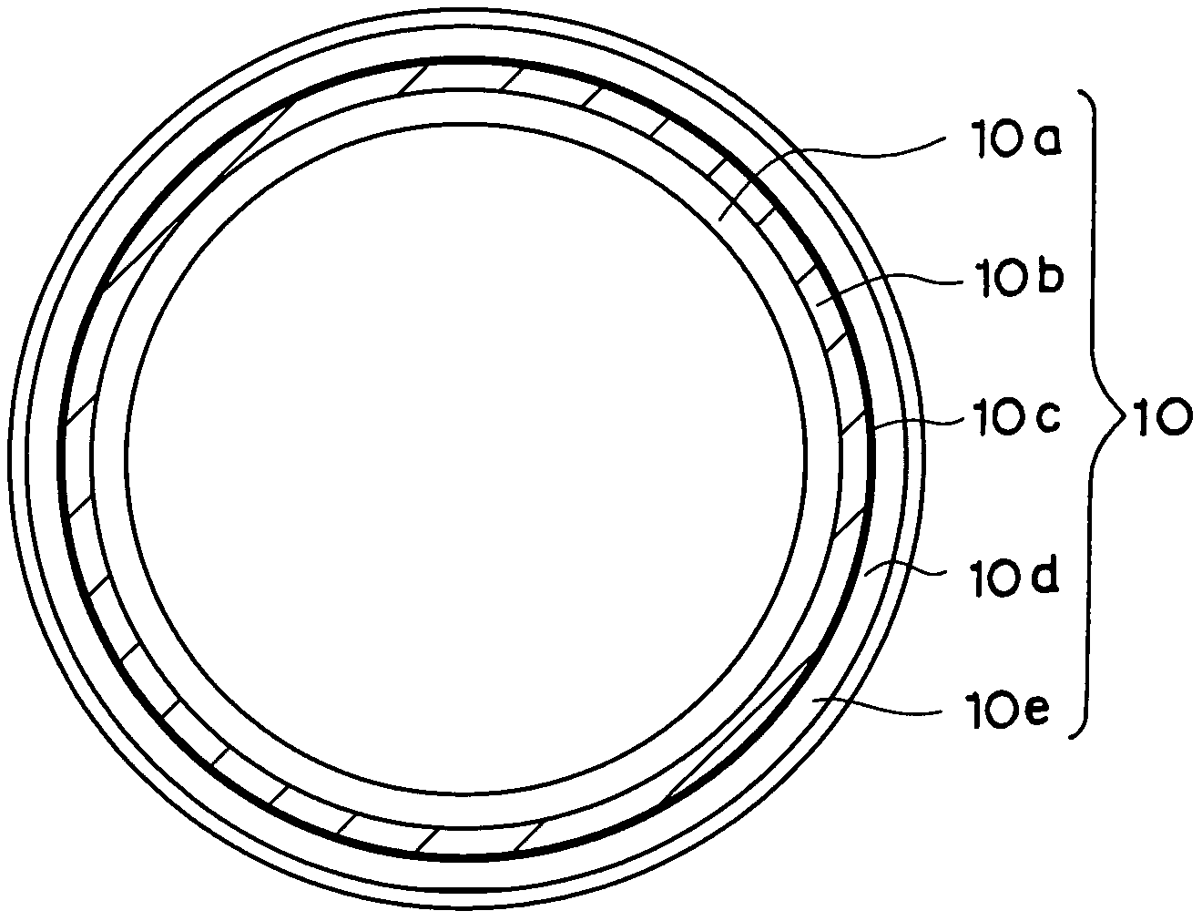
[0156]An endless belt having a film thickness of 60 μm and an outer diameter of 30 mm is prepared using a polyimide resin (trade name: U varnish-S, manufactured by Ube Kosan, Co., Ltd.) As a material of heat resistant resin layer. Next, the outer peripheral surface of this endless belt is subjected to an alkali etching treatment and washing, and the outer peripheral surface of the belt is subjected to an electroless nickel plating to form a nickel layer having a thickness of 0.5 μm. Next, by using the electroless nickel plated layer as an electrode, a copper layer (inner peripheral side metal layer) having a layer thickness of 10 μm is formed on the nickel plated layer by an electroplating treatment. As the electroplating conditions, a plating liquid containing copper sulfate (70 g / L), sulfuric acid (200 g / L), and hydrochloric acid (50 mg / L), is used and the current density is made to 0.2 A / dm2.

[0157]Thereafter, a nickel...

example b

Examples 1-3, Comparative Example 1

-Preparation of Fixing Belt-

[0194]An endless belt having a film thickness of 60 μm and an outer diameter of 30 mm is prepared using a polyimide resin (trade name: U varnish-S, manufactured by Ube Kosan, Co., Ltd.) as a material of heat resistant resin layer. Next, the outer peripheral surface of this endless belt is subjected to an alkali etching treatment and washing, and the outer peripheral surface of the belt is subjected to an electroless nickel plating to form a nickel layer having a thickness of 0.5 μm. Next, by using the electroless nickel plated layer as an electrode, a copper layer (inner peripheral side metal layer) having a layer thickness of 10 μm is formed on the nickel plated layer by an electroplating treatment. The composition of the copper electroplating liquid is shown in Table 8 below.

[0195]Here, four samples having different internal stresses are prepared by adjusting the current density, and changing the kinds and addition amo...


PUM


Abstract

The present invention provides a fixing member having a heat resistant resin layer, a metal layer having two or more layers, and a releasing layer, in this order from the inner peripheral side, wherein a specific resistance of the metal layer disposed at the outer peripheral side is larger than a specific resistance of the metal layer disposed at the inner peripheral side in the at least two metal layers, and a modulus of an internal stress of the metal layer disposed at the outer peripheral side is 5 kg / mm2 or less. Further, a fixing device includes the fixing member, an electromagnetic induction heating device in which an electric field is applied to the fixing member, and a press member which press-contact the surface of a releasing layer of the fixing member. Furthermore, an image forming device having this fixing device is provided.

Description

CROSS-REFERENCE TO RELATED APPLICATION[0001]This application claims priority under 35 USC 119 from Japanese Patent Application Nos. 2005-84971 and 245826, the disclosures of which are incorporated by reference herein.BACKGROUND OF THE INVENTION[0002]1. Field of the Invention[0003]The present invention relates to a fixing member for an electromagnetic induction heating for use in a device utilizing an electrophotographic system such as a copier, a printer or the like, to a fixing device using an electromagnetic induction heating method, and to an image forming device having the fixing device.[0004]2. Description of the Related Art[0005]In an image forming device such as a copier or a printer employing an electrophotographic system, the process of fixing a toner image formed on a recording material such as paper to make a permanent image has been conventionally called a “fixing process”. Conventional fixing processes include methods of press fixing, oven fixing, and solvent fixing, ho...

Claims


Application Information

Patent Timeline
Patent Type & Authority Patents(United States)
IPC IPC(8): G03G15/20
CPCG03G15/2057G03G2215/2035
Inventor HIGASHI, TAKETOSHIOHTA, SHIGEOOMATA, MAKOTOSAITOU, MASATO
Owner FUJIFILM BUSINESS INNOVATION CORP
Features
  • R&D
  • Intellectual Property
  • Life Sciences
  • Materials
  • Tech Scout
  • Unparalleled Data Quality
  • Higher Quality Content
  • 60% Fewer Hallucinations
Learn More