Filter device and parts thereof and a method for operating of the filter device

a filter device and filter body technology, applied in the direction of filtering separation, moving filter element filters, separation processes, etc., can solve the problem of increasing the differential pressure of the filter device, and achieve the effect of reducing installation space and low production costs

Active Publication Date: 2008-10-14
HYDAC FILTERTECHNIK GMBH
View PDF13 Cites 15 Cited by
  • Summary
  • Abstract
  • Description
  • Claims
  • Application Information

AI Technical Summary

Benefits of technology

[0004]An object of the present invention is to provide an improved filter device having low production costs, reduced installation space, and a blocking solution whi

Problems solved by technology

If the fluid flow through the filter device is completely stopped by the valve, the hydraulic control unit evaluates this as a problem, resulting in an error report being delivered from which the operating or maintenance personal can then detect the absence of the filter element or by choking

Method used


Image

  • Filter device and parts thereof and a method for operating of the filter device
  • Filter device and parts thereof and a method for operating of the filter device
  • Filter device and parts thereof and a method for operating of the filter device

Examples


Embodiment Construction

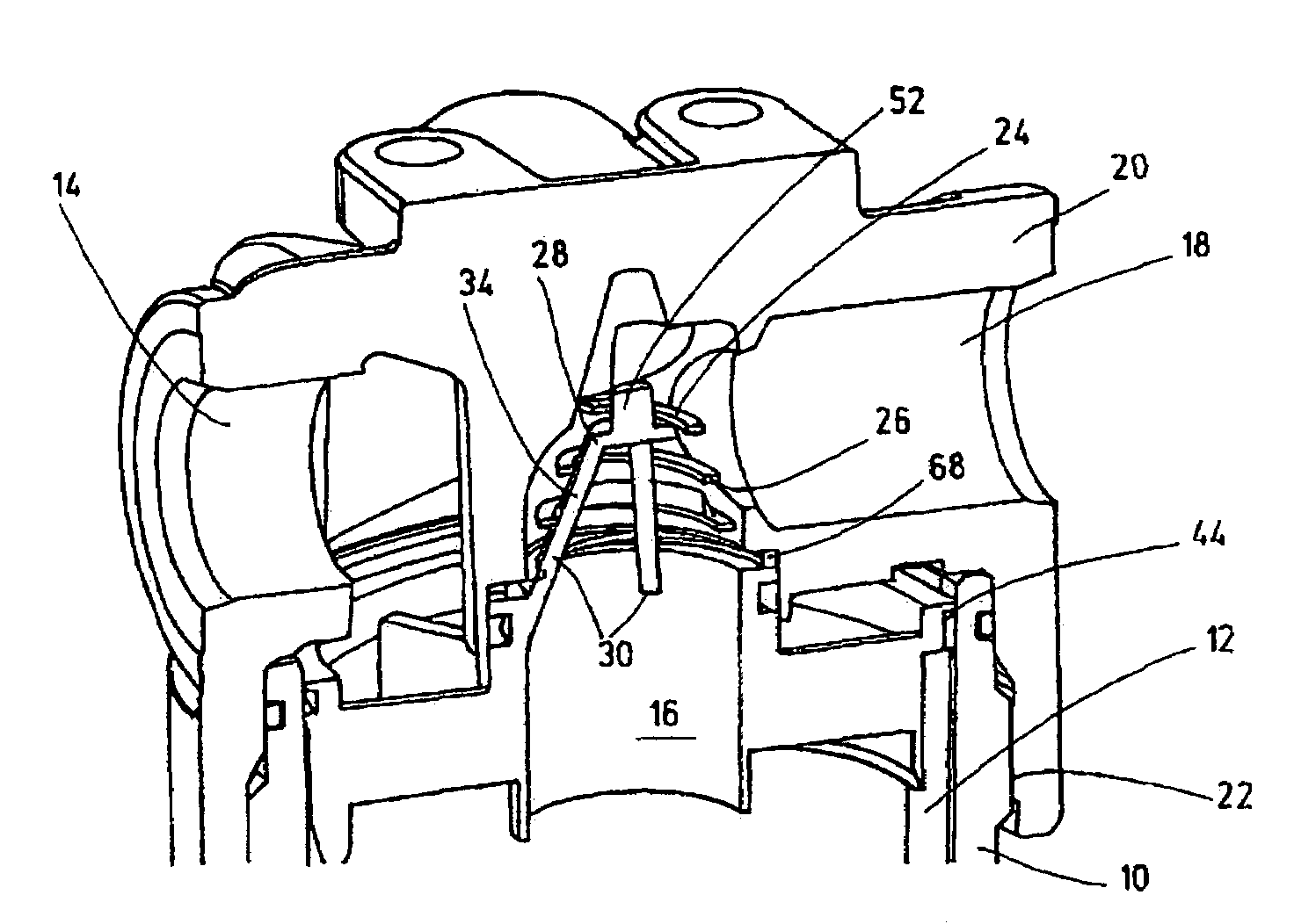
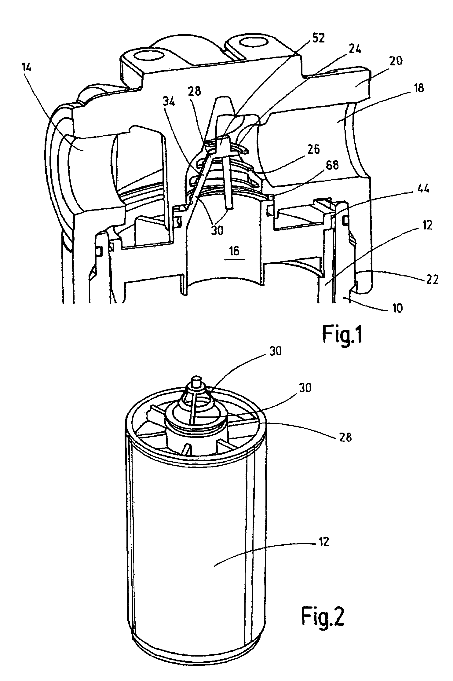
[0020]The filter device shown in FIG. 1 has a cup-shaped filter housing part 10 surrounding the filter element 12, as is shown, for example, in FIG. 2. Flow takes place through the filter element 12 from the outside to the inside, as viewed in FIG. 1. The filter element has a conventional filter element structure which is not detailed, for example, comprising a pleated, multilayer filter mat supported against a fluid-permeable support pipe. Fouled fluid is optionally supplied from a hydraulic circuit (not detailed) via the fluid supply 14 to the filter device. Cleaned, filtered fluid travels via a center channel 16 of the filter element 12 to the fluid discharge 18 of the filter device. To be able to backflush the filter element 12, it would also be conceivable to operate the filter device in the reverse fluid direction. Likewise, it would be possible in a specially designed filter element 12 to reverse the direction of fluid throughflow so that then the fluid to be cleaned flows th...


PUM


Abstract

A filter device has a filter housing part (10) with a filter element (12) and can be detachably connected to another filter housing part (20). A valve (24) clears a fluid path in the interconnected state of the housing parts (10, 20) with the filter element, and in the separated state of the housing parts (10, 20) from one another or without the filter element at least partially blocks it. Instead of known quarter-turn fastener and stopper solutions, a blocking is devised which can be economically implemented and which requires decidedly less installation space. A process for operation of a filter device is also provided.

Description

FIELD OF THE INVENTION[0001]The present invention relates to a filter device having a filter housing part comprising a filter element and detachably connected to another filter housing part. The present invention furthermore relates to certain parts of the filter device and a method for its operation.BACKGROUND OF THE INVENTION[0002]The prior filter devices include, among others, so-called spin-on filters. In their filter housing parts, a filter element designed especially for the respective filtration task is integrated. If the filter element is clogged with dirt causing the filter device to become unusable for its filtration task, the entire filter device, that is, the filter housing in addition to the filter element, must be replaced by a new filter device. This replacement has the disadvantage that the entire unit must be disposed of, although the actual filter housing part would still be usable. To remedy this situation, conventionally in the spin-on filter only the used filter...

Claims


Application Information

Patent Timeline
IPC IPC(8): B01D35/153
CPCB01D35/143B01D35/147B01D2201/16Y10S251/902Y10T137/784
Inventor KLEIN, VOLKMAR
Owner HYDAC FILTERTECHNIK GMBH
Why Eureka
Try Eureka