Positioning control apparatus and the method

a technology of positioning control and control apparatus, which is applied in the direction of automatic control, process and machine control, instruments, etc., can solve the problems of excessive high torque that needs to be applied to the motor, oscillation and divergence, damage to the gimbal and the driving system, etc., and achieve accurate positioning control

Inactive Publication Date: 2008-10-14
FUJITSU LTD
View PDF10 Cites 5 Cited by
  • Summary
  • Abstract
  • Description
  • Claims
  • Application Information

AI Technical Summary

Benefits of technology

[0060]An object of the present invention is to provide a positioning control apparatus and the method in which the above problems are solved and switching between control modes are performed smoothly with high precision.
[0061]More particularly, the object of the present invention is to provide a gimbal control apparatus and the method in which suppression ability against disturbance is improved, the gimbal can be controlled in a state where spatial stabilizing control error for the optical axis is very small, and tracking at the time of switching can be performed with small torque without time for waiting for start of switching for judgment.
[0062]In addition, the object of the present invention is to provide a gimbal control apparatus and the method in which stable tracking operation can be performed and the gimbal can be driven by a small motor of small output torque at the time of stop / restart at the mecha-limit point.
[0065]According to the present invention, since control of the control mode before being switched is reflected in the control mode after being switched, accurate positioning control which enables smooth switching between control modes can be realized.

Problems solved by technology

Since the feedback signals and control methods used in the angle loop and the angular velocity loop are different, excessively high torque is need to be applied to the motor if the control blocks are simply switched.
Thus, oscillation and divergence occur due to the excessive output torque.
For example, in the angular velocity control mode with respect to space M3, when continuing to provide an instruction to move the optical axis to the mecha-limit angle direction, heavy collision occurs at the mecha-limit position so that the gimbal and the driving system are damaged if a means of avoiding the collision is not provided.
For example, in the angle control mode with respect to space M2, when the optical axis is spatially stabilized in the vicinity of the mecha-limit, that is, when shaking is corrected, there may be cases where the optical axis can not be stabilized since shaking can not be fully corrected within the gimbal operating range according to shaking condition.
However, there are following problems in the first to third conventional examples.
However, accuracy of positioning is bad, and response speed is low.
In addition, there are problems in that, it is necessary to use a large torque motor which can output a torque for tracking response to angular velocity disturbance which is applied like steps, and the bore or the length of the motor becomes large.
However, a switch waiting time becomes necessary, and it may occur that switching start time becomes long according to a ship shaking condition.
In addition, there is a problem in that tracking operation becomes unstable due to that a ship gyro signal shaped like step is applied when switching.
Therefore, large torque is necessary for switching in a shaking condition.
Thus, switching process is difficult.
In addition, normally, since drift is included in the angle sensor itself, there is a problem in that the optical axis is drifted when control by the angular velocity instruction is performed.
Therefore, the step-like disturbance can not be removed so that tracking operation becomes unstable.
Although this method is a general method for restricting operation in the vicinity of mecha-limit, large step-like torque occurs due to deceleration / acceleration when stop / retracking occurs for switching at the limit point.
Therefore, smooth stop / smooth retracking can not be performed, so that the gimbal may oscillate in some cases when switching is performed.
In the conventional methods of the first and second methods, since tracking is performed according to judgment condition of the switching processing part, high speed response ability for tracking is not realized.
In addition, since the control is performed only by the angle loop and the angular velocity loop, the gimbal control error becomes large so that high performance can not be obtained.
However, there is a defect in that a positioning space of the speed reducer is necessary, response performance for the angle, the angular velocity and the angular acceleration is sacrificed.

Method used


Image

  • Positioning control apparatus and the method
  • Positioning control apparatus and the method
  • Positioning control apparatus and the method

Examples


first embodiment

[0101]First, a first embodiment of the present invention on switching between three control modes M1-M3 from power-on to stop will be described.

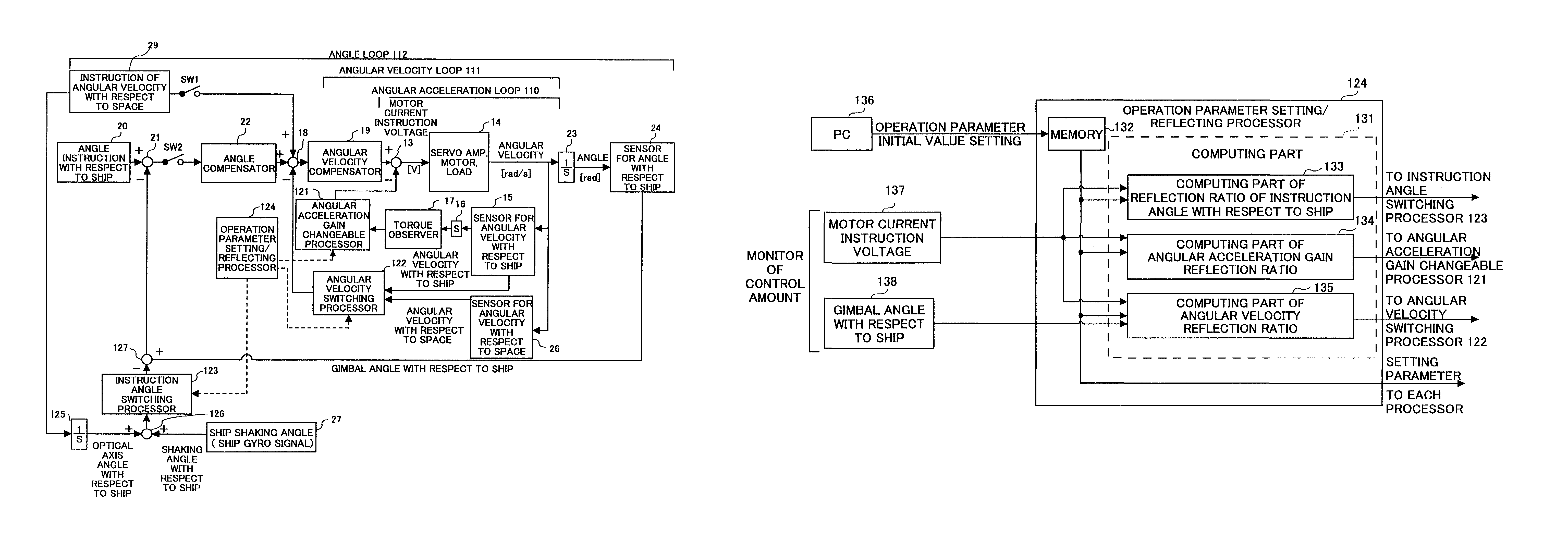
[0102]FIG. 11 is a block diagram showing a gimbal control apparatus according to the first embodiment of the present invention. In FIG. 11, same reference numbers are assigned to features same as those in the above mentioned configuration.

[0103]The gimbal control apparatus shown in FIG. 1 includes an angular acceleration loop 110, an angular velocity loop 111 and an angle loop 112. One of the characteristic of the present invention is that an angular acceleration gain changeable processor 121 is provided in the angular acceleration loop 110, an angular velocity switching processor 122 is provided in the angular velocity loop 111, an instruction angle switching processor 123 with respect to ship is provided in the angle loop 112, and an operation parameter setting / reflecting processor 124 for controlling the processors 121-123 are provided.

[0...

second embodiment

[0116]FIG. 13 is a block diagram showing a gimbal control apparatus according to the second embodiment of the present invention. In FIG. 13, same reference numbers are assigned to features same as those in the above mentioned configuration. The second embodiment relates to a switching method of the three control modes M1-M3 in the vicinity of the gimbal mecha-limit angle.

[0117]The configuration shown in FIG. 13 includes an angular velocity switching processor 122, an angle / angular velocity limit processor 140 provided in the angle loop 112A, and a processor 123 for switching instruction angle with respect to ship, wherein the angular velocity switching processor 122 changes a reflection ratio of an output signal of the angular velocity sensor 15 with respect to ship which detects an angular velocity with respect to ship and an output signal of the angular velocity sensor 26 with respect to space which detects angular velocity with respect to space according to an angle. The angle / an...

example

[0123]FIG. 16 shows an example of the present invention. In the figure, the same reference numbers are assigned to the same configuration elements described before.

[0124]FIG. 16 shows a configuration which includes both of the configurations of the first embodiment and the second embodiment. In the configuration shown in FIG. 16, a processor 147 of storing angle with respect to ship is added to the configuration shown in FIG. 13. The processor 147 for storing angle with respect to ship stores an optical axis angle with respect to ship according to the gimbal angle with respect to ship. The optical axis angle with respect to ship corresponds to an output signal of the integrator 125 shown in FIG. 13.

[0125]The function of the processor 147 for storing angle with respect to ship will be described in relation to the switches SW1 and SW2. When the mode is in the angular velocity control mode with respect to space M3, the switch SW2 which functions as an angle loop reflection switch is tu...


PUM


Abstract

A positioning control apparatus including feedback loops according to a plurality of control modes which control positioning of an object to be controlled is provided, in which the positioning control apparatus includes a part (121, 122, 123, 124) for reflecting a control process performed by a control mode before being switched in a control process performed by a control mode after being switched when a control mode is switched to another control mode. For example, an operation parameter on the control mode before being switched is dynamically reflected in the control mode after being switched.

Description

BACKGROUND OF THE INVENTION[0001]1. Field of the Invention[0002]The present invention relates to a method of switching control for suppressing required torque and realizing high optical axis stability in a space stabilizer in an infrared imaging device and the like which is mounted on an airplane or a ship.[0003]2. Description of the Related Art[0004]The space stabilizer includes a so-called gimbal. The gimbal is an apparatus (mechanism) for keeping an object to be controlled such as a compass or a camera to be horizontal.[0005]FIG. 1 is a figure for explaining a general control mode of a gimbal. The following explanation is for a control example in which the gimbal is mounted in a ship.[0006]There are three gimbal control modes as shown in FIG. 1. The three gimbal control modes are an angle control mode with respect to ship M1, an angle control mode with respect to space M2 and an angular velocity control mode with respect to space M3. Each mode has following functions.[0007]The an...

Claims


Application Information

Patent Timeline
Patent Type & Authority Patents(United States)
IPC IPC(8): G06F19/00G05D1/08G05B7/02H01Q1/12H01Q3/08
CPCH01Q1/12H01Q1/125H01Q3/08
Inventor MURAKADO, KENICHI
Owner FUJITSU LTD
Why Eureka
Try Eureka