
Method and apparatus for controlling a vehicle door

Inactive Publication Date: 2008-10-21
AMERICAN VEHICULAR SCI
View PDF47 Cites 95 Cited by
  • Summary
  • Abstract
  • Description
  • Claims
  • Application Information

AI Technical Summary

Benefits of technology

[0042]It is another object of the present invention to provide new and improved door mechanisms which enables the door to be moved to a plurality of different open positions and held in those open positions.
[0043]It is still another object of the present invention to provide new and improved door check mechanisms which provide positive retention of the vehicle door in an infinite number of open positions without interfering with the normal opening and closing movements of the doors, yet exhibit long life and are essentially unaffected by high or low temperatures.
[0044]Further objects and advantages on this invention include, to provide an infinite position door check mechanism which does not require lubrication; has an operating life equivalent to that of the vehicle; does not corrode; is able to endure vehicle body processing temperatures associated with the curing of external finishes (about 400° F.); is able to be easily separated from the vehicle after painting to permit the door to be separately trimmed and then reassembled to the body; is simple and inexpensive to manufacture and install; does not result in unacceptable stress and wear on the door hinges caused by loading from the door check; does not require post installation adjustment during the vehicle life; and has the capability to be released electrically permitting the vehicle door to close under its own weight.
[0045]It is another object of the present invention to provide new and improved motorized swing doors wherein provisions are made to allow the door to be opened manually without damaging the actuating motor.
[0046]It is yet another object of the present invention to provide a new and improved motorized swing doors which can be opened by an authorized person from a distance using for example a key or other unique object.

Problems solved by technology

However, they are far from uniform in construction or in application.
None has yet achieved commercial success due to the cost and complexity and well as the short service lives of these prior art mechanisms.
Door check mechanisms have in general exhibited some substantial difficulties over the years including: (i) the need in some designs for frequent lubrication without which they tend to make undesirable noises; (ii) inadequate operating life; (iii) corrosion; (iv) the inability to endure vehicle body processing temperatures associated with the curing of external finishes (400° F.
); (v) the inability to be easily separated from the vehicle after painting to permit the door to be separately trimmed and then reassembled to the body; (vi) the occurrence of unacceptable stress and wear on the door hinges caused by loading from the door check; and (vii) the requirement for frequent post installation adjustment during the vehicle life.
Each of these problems has been addressed in one or more of the prior art fixed detent door checks but there is no infinite door check that has solved all of these problems.
Such a tendency, when in the closing direction, causes the door to strike the legs or other parts of a person entering or leaving the automobile.
When in the opening direction, it can cause the door to impact into other people or objects inflicting harm or damage thereto.
A particularly costly problem, as reported by automobile insurance companies, happens in parking lots where the opening door of one vehicle bangs into an adjacent vehicle causing damage to the finish that can lead to an insurance claim.
This increases the cost of insurance to all automobile owners.
The effectiveness of this system is degraded when the coefficient of friction changes, and the system has a limited life.
Problems arise with regard to dirt, moisture, temperature, wearing etc.
The continuous friction defeats the automatic door closing system.
The frictional locking mechanism is held in contact with the friction surfaces by means of a biasing spring that exerts its maximum torque and thus creates the maximum wear when the mechanism is in the unlocked position.
The system requires careful alignment and is subject to wear.
The frictional drag works to prevent the door from closing under its own weight thus defeating that desirable function.
Although this is the goal, this cannot be achieved due to surface contamination.
This may cause significant motion of the door to get to the nearest door detent.
There also is an alignment problem with this device.
The device is complicated, requires adjustment, is sensitive to dirt, and has no positive intermediate position.
The friction surfaces are knurled and adjustment is required during the life of the vehicle due to wear of brake surfaces.
The checking motion is rather small, probably resulting in significant variation in the checked position from vehicle to vehicle.
It uses a roller that rubs continuously on the friction surface resulting in a wear problem.
For this reason, the hard rubber chosen as the friction surface is a poor choice since the friction coefficient is strongly influenced by surface films.
This is unsustainable as surface films will radically change the friction coefficients.
Since significant friction is always present, there is a wear problem resulting in a device with a short life without adjustment.
The ball system gives point contact, therefore higher forces and therefore greater wear.
Although the ball rolls in the groove, on which the patent makes a great issue, it is sliding on the elastomeric spring that pushes it down.
This sliding friction will cause wear and shorten the life of the door check.
There is no obvious advantage to this overly complicated system since to deactivate the door holding system, the door must be moved which requires a force.
However, in this case, the hinge pin is still loaded when the door is moved into and out of the detented positions and thus the problem is only partially solved.
As a result, there is no successful infinite door check in high volume commercial use at this time although the desire for such a device is well known in the industry.

Method used


Image

  • Method and apparatus for controlling a vehicle door
  • Method and apparatus for controlling a vehicle door
  • Method and apparatus for controlling a vehicle door

Examples


Embodiment Construction

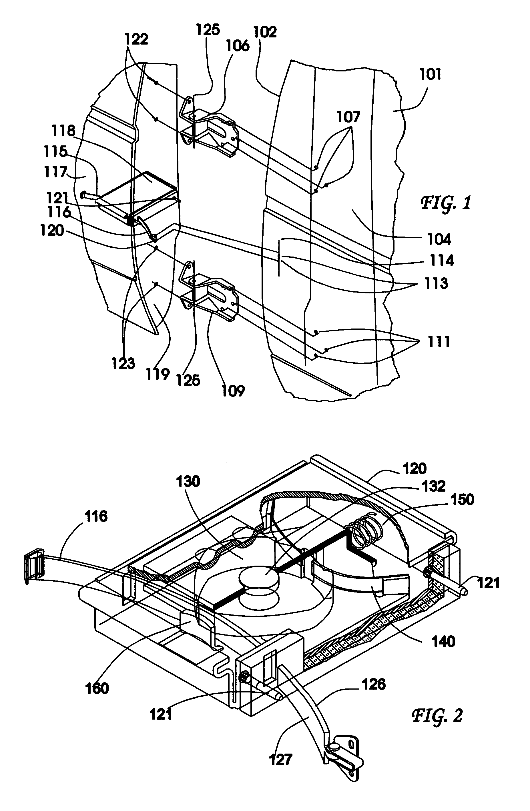
[0097]Referring to the accompanying drawings wherein like reference numerals refer to the same or corresponding parts throughout the several views, FIG. 1 is a partially exploded perspective view of a portion of the side of a vehicle, which could be an automobile or virtually any other kind of vehicle, including a part of a door opening. A portion of the right front side body of the vehicle is shown at the right-hand side and a portion of the door is shown on the left-hand side of FIG. 1 respectively. The edge of the door opening, along the left-hand vertical side of body member 101, is identified by reference numeral 102. Closely adjacent to the edge of the door opening 102, there is a vertical frame member 104, a part of the vehicle frame that may be the A-pillar. The terms vertical frame member and A-pillar are used interchangeably herein although the vertical frame pillar may be other than the A-pillar such as the B-pillar if the door is a rear door of a four door vehicle.

[0098]...


PUM


Abstract

Vehicle including a door frame alongside a position in a passenger compartment of the vehicle normally occupied by a driver, a driver door having a first, closed position arranged in the door frame and a second, fully open position outside of the door frame, and an infinite door check mechanism which enables the door to be moved between the first and second positions and to any open position therebetween. The infinite door check mechanism includes a motor arranged to move the door between the first and second positions and to any of the open positions therebetween. A control mechanism controls the motor to initiate movement of the door and stop the movement when the door is in any one of the different open positions and maintain the door in the stopped position in the absence of applied force to hold the door in the stopped position.

Description

CROSS-REFERENCE TO RELATED APPLICATIONS[0001]This application is a continuation-in-part of U.S. patent application Ser. No. 10 / 657,547 filed Sep. 8, 2003 which is:[0002]1) a continuation-in-part of U.S. patent application Ser. No. 10 / 397,950 filed Mar. 26, 2003, now U.S. Pat. No. 6,928,694;[0003]2) a continuation-in-part of U.S. patent application Ser. No. 10 / 043,556 filed Jan. 11, 2002, now U.S. Pat. No. 6,681,444, which is a continuation-in-part of U.S. patent application Ser. No. 09 / 576,065 filed May 22, 2000, now U.S. Pat. No. 6,349,448, which is a continuation of U.S. patent application Ser. No. 09 / 040,206 filed Mar. 17, 1998, now U.S. Pat. No. 6,065,185, which claims priority under 35 U.S.C. §119(e) of U.S. provisional patent application Ser. No. 60 / 040,977 filed Mar. 17, 1997; and[0004]3) claims priority under 35 U.S.C. §119(e) of U.S. provisional patent application Ser. No. 60 / 409,756 filed Sep. 11, 2002.[0005]All of the above-mentioned applications are incorporated by refer...

Claims


Application Information

Patent Timeline
IPC IPC(8): B60J5/00
CPCE05C17/203E05C17/006E05D15/30E05Y2900/531
Inventor BREED, DAVID S.
Owner AMERICAN VEHICULAR SCI
Learn More