
Method and system using liquid dielectric for electrostatic power generation

a technology of electrostatic power generation and liquid dielectric, applied in the field of electric production, can solve the problems of insufficient power supply for conventional electromagnetic generators, ineffective power supply for applications, and limitations of electromagnetic generators, and achieve the effects of high reliability, high uniformity, and easy wear and tear

Inactive Publication Date: 2008-11-04
CALIFORNIA INST OF TECH
View PDF14 Cites 28 Cited by
  • Summary
  • Abstract
  • Description
  • Claims
  • Application Information

AI Technical Summary

Benefits of technology

The electret device provides a reliable and efficient method for generating power, achieving high uniformity and long-lasting operation with minimal wear and tear, suitable for small-scale applications.

Problems solved by technology

Although highly effective for certain applications, electromagnetic generators have limitations as they become smaller and smaller.
As merely an example, electromagnetic generators have been ineffective for providing power for applications having a form factor of less than one cubic centimeter.
Conventional electromagnetic generators often cannot provide enough power as the size of the armature becomes less than an inch to operate many modern electronic devices such as cell phones, personal digital assistants, pagers, pace makers, and the like.
The peak power output from these generators is less than 40 microwatts, and not sufficient for continuous operation of the watch hands.
Functionality of the watch is sacrificed due to the lack of a sufficient power supply.
Accordingly, modern electronic devices still rely upon power from chemical power sources such as batteries, which often have a fixed life, are difficult to charge, and cumbersome.
Unfortunately, conventional electret generators still lack a capability of becoming smaller and more effective and have not seen any commercial use.

Method used


Image

  • Method and system using liquid dielectric for electrostatic power generation
  • Method and system using liquid dielectric for electrostatic power generation
  • Method and system using liquid dielectric for electrostatic power generation

Examples


Embodiment Construction

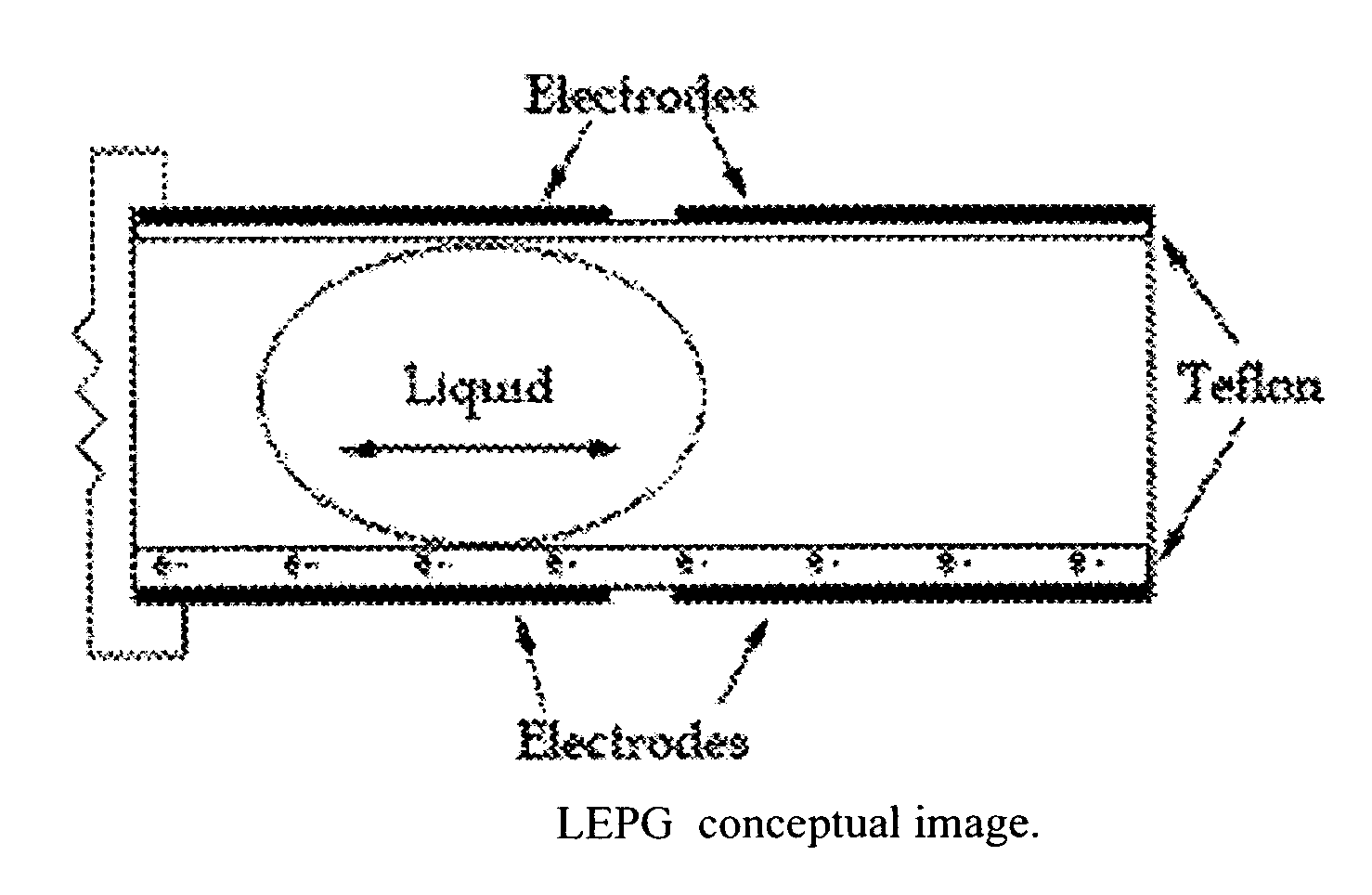
[0034]According to the present invention, techniques related to electrical production are provided More particularly, the invention provides a method and resulting device for fabricating an electret device having a liquid dielectric entity for generation of electrical power. Merely by way of example, the electret device has been fabricated using a patterning process including micromachining processes. But it would be recognized that other processes such as molding, casting, laser ablation, direct printing, etc. can also be used. Additionally, the liquid dielectric entity can be any movable liquid (or certain other fluids), solid entities, which may behave like a liquid, any combination of these, and the like.

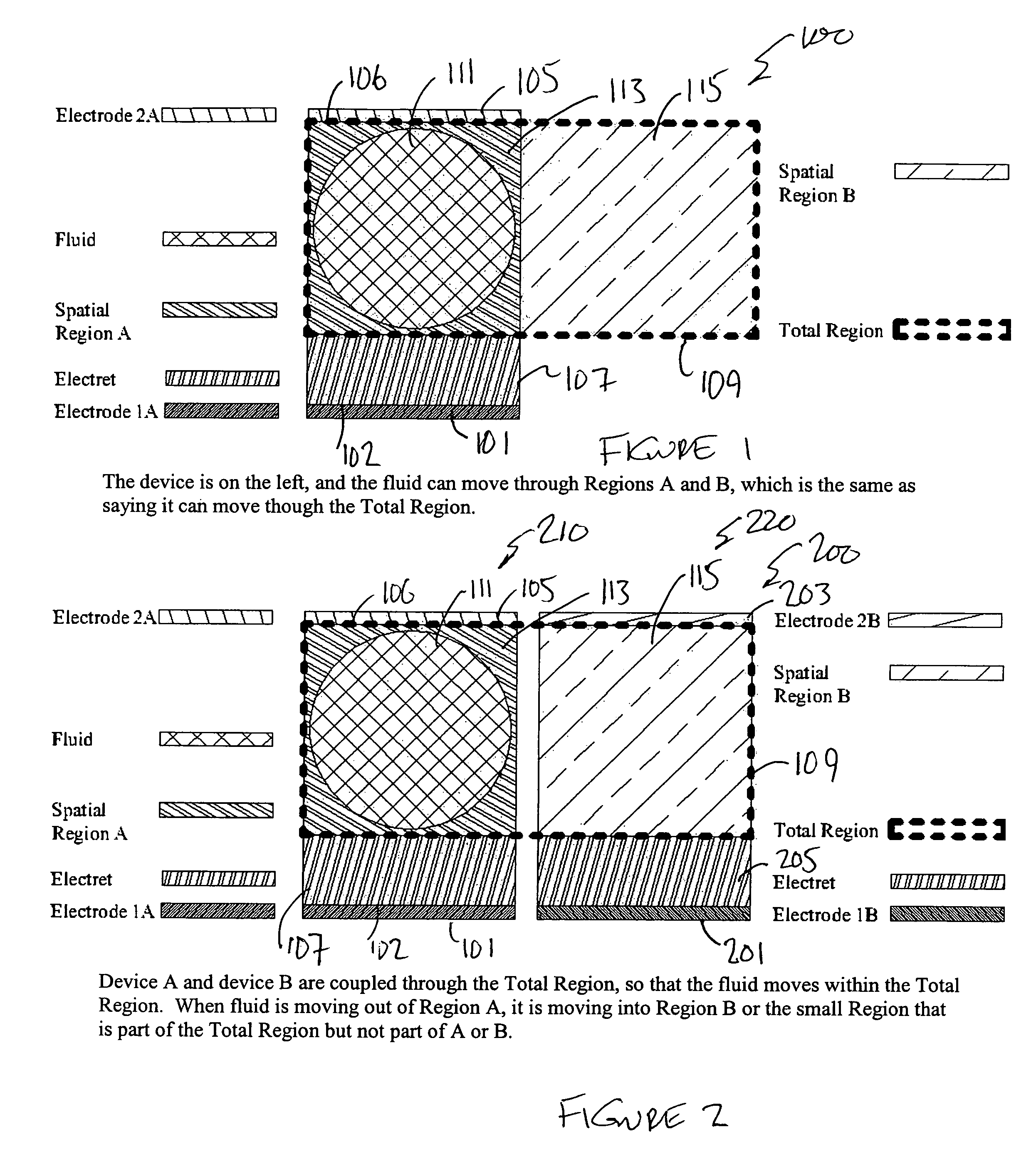
[0035]FIG. 1 is a simplified diagram of an electret power generating device 100 according to an embodiment of the present invention. This diagram is merely an illustration, which should not unduly limit the scope of the claims herein. One of ordinary skill in the art would recog...


PUM


Abstract

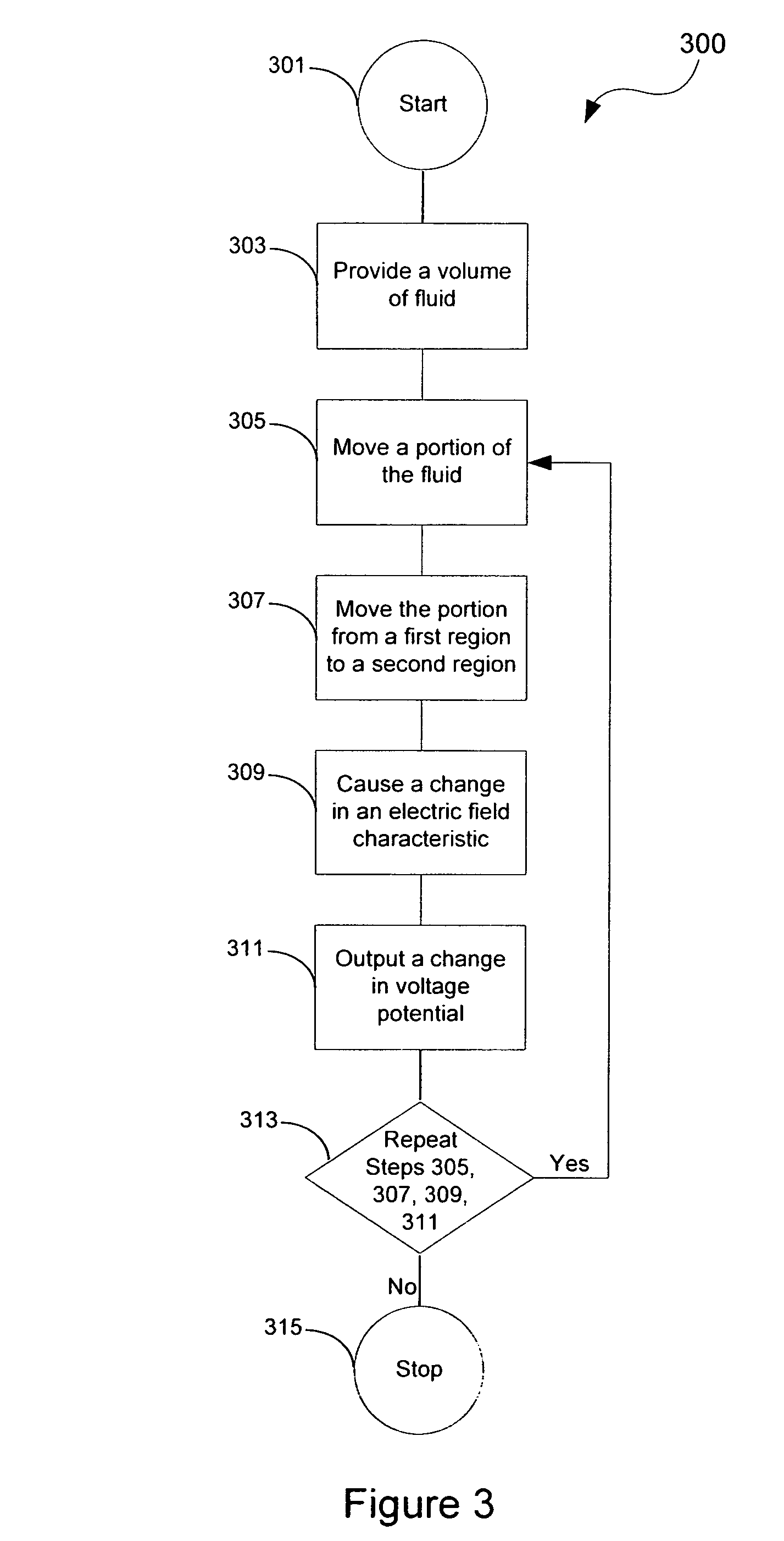
A system and method for generating power. The system has a first electrode member comprising a first region and a second electrode member comprising a second region. Preferably, the second electrode member is coupled to the first electrode member. An electret is coupled between the first electrode member and the second electrode member. The system has a spatial region provided between the first region of the first electrode member and the second region of the second electrode member. A volume of fluid (e.g., liquid, liquid and solids, gas and liquid, solids and gases) is provided between the first region and the second region and is adapted to move between the first region and the second region to cause a change in an electric field characteristic within a portion of the spatial region by the movement of at least a portion of the fluid within the portion of the spatial region to generate a change in voltage potential between the first electrode and the second electrode.

Description

CROSS-REFERENCES TO RELATED APPLICATIONS[0001]This present application claims priority to U.S. Provisional Patent Applications Nos. 60 / 577,904 (CIT No. 4125-P) filed Jun. 7, 2004, 60 / 578,117 (CIT No. 4126-P) filed Jun. 7, 2004, and 60 / 577,864 (CIT No. 4127-P) filed Jun. 7, 2004, each of which is in the names of Justin Boland and Yu-Chong Tai, commonly owned, and hereby incorporated by reference for all purposes.STATEMENT AS TO RIGHTS TO INVENTIONS MADE UNDER FEDERALLY SPONSORED RESEARCH OR DEVELOPMENT[0002]This work was partially supported by DARPA under Award Number DAAH01-01-R002.REFERENCE TO A “SEQUENCE LISTING,” A TABLE, OR A COMPUTER PROGRAM LISTING APPENDIX SUBMITTED ON A COMPACT DISK[0003]NOT APPLICABLEBACKGROUND OF THE INVENTION[0004]The present invention generally relates to electrical production. More particularly, the invention provides a method and resulting device for fabricating an electret device having a liquid dielectric entity for generation of electrical power. Me...

Claims


Application Information

Patent Timeline
Patent Type & Authority Patents(United States)
IPC IPC(8): G21D7/02F02B63/04H02K44/00H02N1/00
CPCH02N1/08H02N11/002
Inventor BOLAND, JUSTIN SCOTTTAI, YU-CHONG
Owner CALIFORNIA INST OF TECH
Learn More