
Multiband monopole antenna with independent radiating elements

a radiating element and antenna technology, applied in the direction of radiating element structure, elongated active element feed, resonance antenna, etc., can solve the problems of multiple antenna feed points, inability to disassemble devices to swap antennas, and inability to meet the needs of users,

Inactive Publication Date: 2008-11-04
DRNC HLDG INC
View PDF9 Cites 50 Cited by
  • Summary
  • Abstract
  • Description
  • Claims
  • Application Information

AI Technical Summary

Benefits of technology

[0010]An antenna is presented that can simultaneously transceive electromagnetic energy in multiple frequency bands, so as to be useful in a device communicating in GSM, TDMA, GPS, and CDMA frequency bands. More specifically, a two-radiator monopole design antenna is described. One radiator can be formed as a meandering microstrip line to operate a relatively low frequencies, i.e., the AMPS band at 800 MHz, while a straight-line microstrip line acts as a higher frequency radiator with a broad bandpass, broad enough to effectively resonate GPS (1575 MHz) and PCS (1900 MHz) frequencies for example. Advantageously, there is a minimum of interaction between radiators, so that the antenna can be formed to fit on flexible materials or on a device case.

Problems solved by technology

Equipping such a wireless device with discrete antenna for each of these frequency bands is not practical as the size of these devices continues to shrink, even as more functionality is added.
Nor is it practical to expect users to disassemble devices to swap antennas.
Even if multiple antennas could be designed to be co-located, so as to reduce the space requirement, the multiple antenna feed points, or transmission line interfaces still occupy valuable space.
The small size makes the helical antenna easy to carry when not attached to the laptop, and unobtrusive when deployed.
However, such a single-coil helical antenna will only operate at one of the frequencies of interest, requiring the user to carry multiple antennas, and also requiring the user to make a determination of which antenna to deploy.
An antenna that depends heavily on the ground plane, such as a patch antenna, planar inverted-F antenna (PIFA), or folded monopole, may perform poorly when a grounded metal is near the antenna in some configurations.
Likewise, the performance of one, ground-dependent, radiator is susceptible to proximately located radiators.
However, any change to one of the radiators affects the performance of others in the series.
This interdependence between radiators makes the antenna difficult to design.
Poor antenna performance can be characterized by the amount of current unintentionally generated through a transceiving device, typically as surface currents, as opposed to amount of energy radiated into the intended transmission medium (i.e., air).
From the receiver perspective, poor antenna performance is associated with degraded sensitivity due to noisy grounds.
From either point of view, poor performance can be associated with radio frequency (RF) ground currents.

Method used


Image

  • Multiband monopole antenna with independent radiating elements
  • Multiband monopole antenna with independent radiating elements
  • Multiband monopole antenna with independent radiating elements

Examples


Embodiment Construction

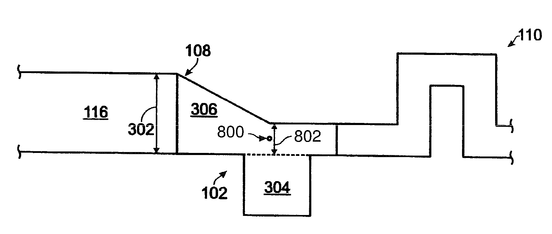
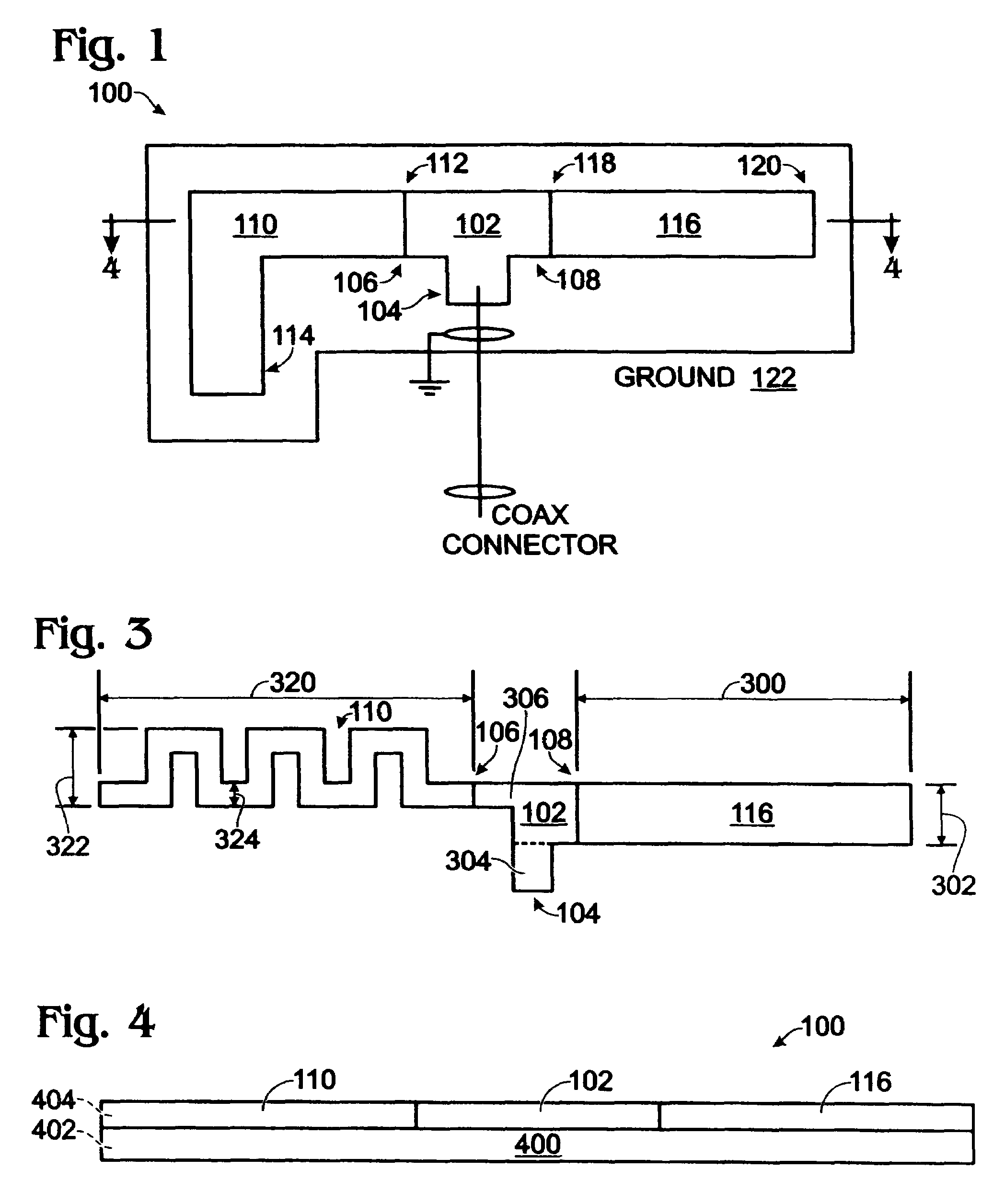
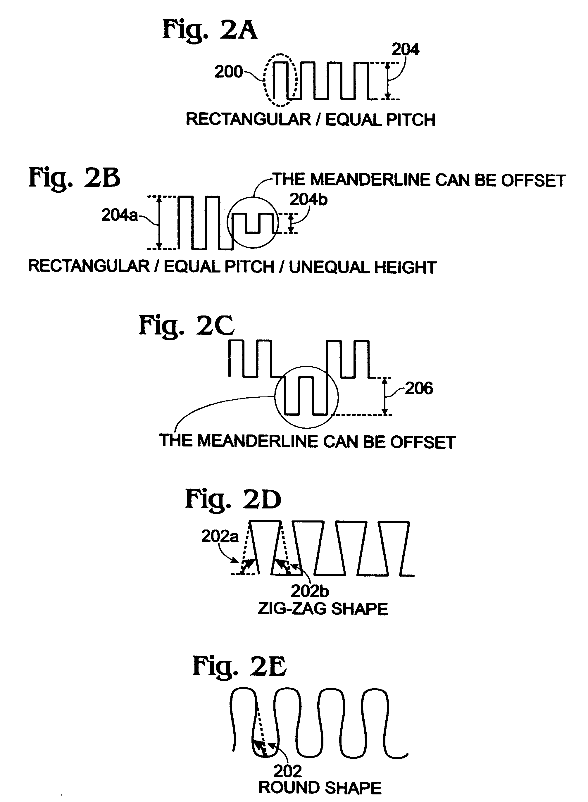
[0029]FIG. 1 is a plan view of a single-feedpoint multiband monopole antenna with independent radiator elements. The antenna 100 comprises a microstrip counterpoise coupler 102 having a single-feedpoint interface 104, a first radiator interface 106, and a second radiator interface 108. A first (right-angle) microstrip radiator 110 has an end 112 connected to the counterpoise coupler first radiator interface 106, and an unterminated end 114. The first microstrip radiator 110 is capable of resonating at a first center frequency. A second microstrip radiator 116 has an end 118 connected to the counterpoise coupler second radiator interface 108, and an unterminated end 120. The second microstrip radiator 116 is capable of resonating at a second center frequency, non-harmonically related to the first frequency. A groundplane 122 is also shown as co-planar. However, in other aspects not shown in this figure, the groundplane can underlie or overlie the radiators 110 / 116.

[0030]FIGS. 2A thro...


PUM


Abstract

A single-feedpoint multiband monopole antenna is provided with independent radiator elements. The antenna comprises a microstrip counterpoise coupler having a single-feedpoint interface, a first radiator interface, and a second radiator interface. A first microstrip radiator, i.e. a meander line microstrip, has an end connected to the counterpoise coupler first radiator interface, and an unterminated end. A second microstrip radiator, i.e. a straight-line microstrip, has an end connected to the counterpoise coupler second radiator interface, and an unterminated end. The two radiators are capable of resonating at non-harmonically related frequencies. As with the two microstrip radiators, the microstrip counterpoise coupler is a conductive trace formed overlying a sheet of dielectric material. The counterpoise coupler can come in a variety of shapes, so that the overall antenna may take on a number of form factors.

Description

RELATED APPLICATIONS[0001]This application is a Continuation-in-Part Application of U.S. application Ser. No. 10 / 818,063, filed Apr. 5, 2004 now U.S. Pat. No. 7,019,696, which is a Continuation Application of U.S. application Ser. No. 10 / 228,693, filed Aug. 26, 2002, now U.S. Pat. No. 6,741,213, the entire disclosures of which are incorporated herein by reference.FIELD OF THE INVENTION[0002]This invention generally relates to wireless communications and, more particularly, to a multiband microstrip monopole antenna, where the radiation patterns are independent of the position of the radiators with respect to each other.BACKGROUND OF THE INVENTION[0003]Wireless communications devices, a wireless telephone or laptop computer with a wireless transponder for example, are known to use simple cylindrical coil antennas as either the primary or secondary communication antennas. The resonance frequency of the antenna is responsive to its electrical length, which forms a portion of the operat...

Claims


Application Information

Patent Timeline
Patent Type & Authority Patents(United States)
IPC IPC(8): H01Q1/38
CPCH01Q1/362H01Q1/38H01Q5/371H01Q9/42H01Q9/40
Inventor NGUYEN, ANTHONY H.JENWATANAVET, JATUPUMHWANG, HUAN-SHENG
Owner DRNC HLDG INC
Learn More