Power control device and method for calibrating the power of a transmitter or receiver in a mobile communication network

a technology of power control device and mobile communication network, which is applied in the direction of transmitter monitoring, receiver monitoring, wireless commuication services, etc., can solve problems such as type approval difficulties, transients, and distortion of signals, and achieve the effect of reducing the number of parts required to implement the tx lineup and reducing costs

Inactive Publication Date: 2008-11-11
NOKIA CORP
View PDF6 Cites 31 Cited by
  • Summary
  • Abstract
  • Description
  • Claims
  • Application Information

AI Technical Summary

Benefits of technology

[0010]The invention provides a device and / or method with enhanced possibility of effective and yet simple power calibration.
[0013]The invention provides a simple and effective calibration system and method.
[0020]The power control may use the training sequence to set the power control and may be employed with any appropriate type of modulation, e.g. Edge or GMSK modulation. This-feature, preferably as part of a system using digital ramping techniques, allows a simple and low cost power control system to be implemented.
[0026]Further, the number of parts required to implement the Tx lineup is reduced, reducing costs.

Problems solved by technology

However, the analog (closed loop) power control schemes as used with GMSK (Gaussian Minimum Shift Keying), have difficulty with EDGE (Enhanced Data for GSM Evolution) 8PSK modulation, as the signal has no longer a constant envelope.
Such as solution is difficult to implement and often causes distortion of the signal due to switching transients caused by the switching of the loop bandwidth.
Transients may also occur when switching between closed loop and open loop operation as the detector range is not sufficient to detect the whole envelope.
Additionally, as the power ramping is controlled by the closed loop, overshoot of the ramp often occurs, giving type approval difficulties.
In the past, beam steering systems have tended to use individual RF line-ups for each transmit path, with the calibration being performed in the baseband processing, which has resulted in very expensive systems.

Method used


Image

  • Power control device and method for calibrating the power of a transmitter or receiver in a mobile communication network
  • Power control device and method for calibrating the power of a transmitter or receiver in a mobile communication network
  • Power control device and method for calibrating the power of a transmitter or receiver in a mobile communication network

Examples


Embodiment Construction

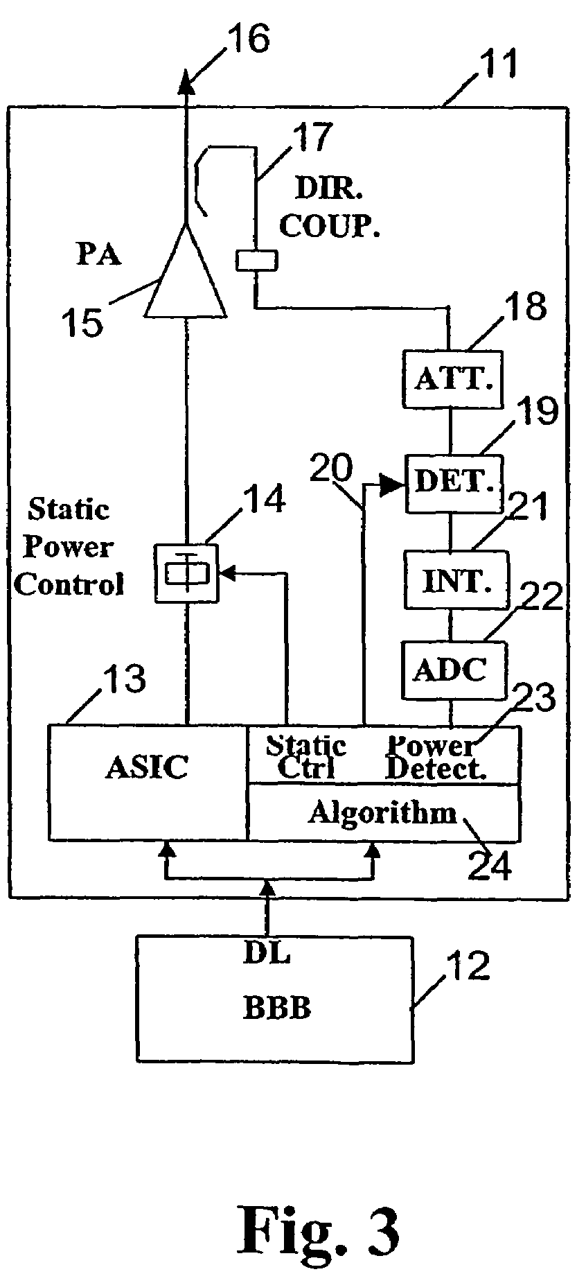
[0036]The described Digital Power Calibration and / or Control scheme in accordance with the invention is for instance applicable in a GSM transceiver. The power calibration and / or control method and devices are designed and applicable for Smart Antenna applications or non Smart Antenna applications. Generally, a smart antenna system combines multiple antenna elements with a signal-processing capability to optimize its radiation and / or reception pattern automatically in response to the signal environment.

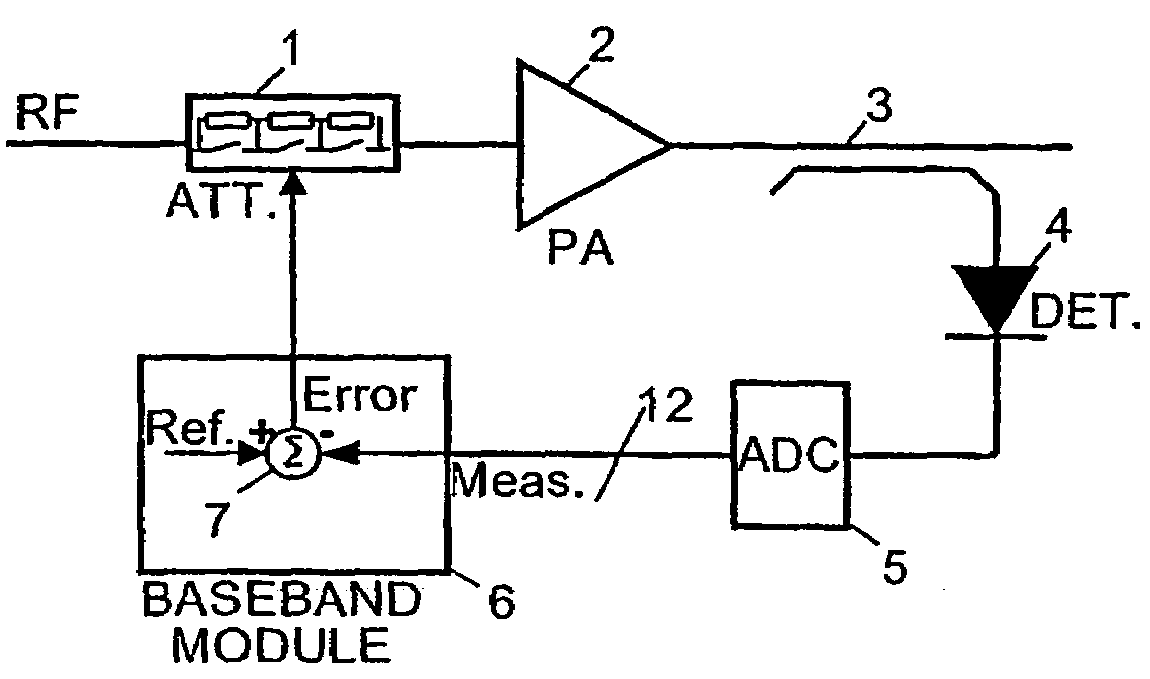
[0037]The purpose of the power control system is to control the output power of the transmitter in several steps, e.g. sixteen steps of 2 dB. Power control is also responsible for meeting the power versus time requirements and switching transient requirements specified in the Digital Cellular Telecommunications System (Phase 2+) for GSM (Global System for Mobile Communications).

[0038]According to a preferred implementation of the invention, the output of the Power Amplifier is detecte...


PUM


Abstract

The invention relates to a power control device and method for calibrating the power of a transmitter or receiver in a mobile communication network comprising an antenna array, wherein burst signals are transmitted to, or received by, the antenna array. The calibration of the transmission or receiving power of the transmitter or receiver includes a summing step for summing transmission or reception signals of the antenna array, and a common calibrating step for commonly calibrating the summed signals.

Description

FIELD AND BACKGROUND OF THE INVENTION[0001]The invention relates to a power control device and method for calibrating the power of a transmitter or receiver of a mobile communication network in which burst signals are applied to the transmitter. The burst signals include a fixed training sequence.[0002]More generally, the invention relates to Power Control, in particular Digital Power Control of a transmitter such as a Transceiver (TRX, e.g. Transceiver Card) or a BTS (Base Transceiver Station) Transmitter. More specifically, the invention aims at providing a power control function applicable to a device, system, and method requiring power calibration.[0003]In existing GSM compatible basestations, Power Control is implemented by a combination of two methods: closed loop, when the transmitter is on, and open loop when the transmitter is off. The closed loop mode is a real time control in which the output power is sampled and compared to a reference signal, and the gain is corrected. ...

Claims


Application Information

Patent Timeline
Patent Type & Authority Patents(United States)
IPC IPC(8): H04B17/00H03G3/30H04B7/005
CPCH03G3/3047H04B17/20H04B17/13H04W52/52
Inventor SHURVINTON, BILL WILLIAMSPINK, DAVID
Owner NOKIA CORP
Why Eureka
Try Eureka