Method for determining time borders and frequency resolutions for spectral envelope coding

a technology of applied in the field of systematic segmentation methods for determining time borders and frequency resolutions of bandwidth expansion technologies, can solve problems such as insufficient methods, and achieve the effect of good sound quality, easy implementation of strategies, and good sound quality

Inactive Publication Date: 2008-11-11
PANASONIC CORP
View PDF18 Cites 26 Cited by
  • Summary
  • Abstract
  • Description
  • Claims
  • Application Information

AI Technical Summary

Benefits of technology

[0017]The spectral coding strategy adopted by the prior art resorts to low time resolution but high spectral resolution (i.e. deriving a frequency spectrum by more frequency bands but few time segments). When a transient is detected, the prior art switches to high time resolution but low spectral resolution (i.e. deriving a frequency spectrum by less frequency bands but more time segments) to code the region after the transient. An objective for switching the degrees of resolution is to account for the fact that the transient tends to exhibit more temporal variation than spectral variation. Lowering the frequency resolution can help curb a sudden surge in bit consumption. However, this method is not sufficient if the post-transient region exhibits a high degree of spectral variation that warrants a higher resolution, such as the case of a sudden burst of a tonal signal.<Determination of Time Borders>
[0026]According to the present invention, a method for determining a time border and a frequency resolution in spectral envelope coding of an audio signal utilizing a time / frequency grid, the method including: deriving a start time border of a current frame from an end time border of a previous frame of envelope data; detecting, by a transient detector, a transient time slot in spectral data between the start time border and the end time border within a predetermined allowed region, a degree of the transient exceeding a certain drasticness; and finding and instantiating an actual end time border and intermediate time borders in the spectral data between the transient time slot and the end time border of the current frame within the predetermined allowed region by comparing the transient drasticness with a predetermined signal variation criterion. By this method, it is possible to realize good sound quality by emphasizing the post-transient region over the pre-transient region, and the region closest to the onset of transient over the region further away, while taking into considerations all imposed syntactic constraints.
[0027]Furthermore, the frequency resolution determination method detects distribution of energy in a frequency direction in the post transient regions. The frequency resolution in a time segment is derived by evaluating energy of every frequency band partitioned by low-resolution borders represented by a predetermined frequency for every time segment obtained by dividing the current frame using the intermediate time borders and the end time border. When a large variation in the energy distribution is detected, this method resorts to high-resolution segmentation. The two methods of the present invention realize a good and easily implemented strategy for segmentation of the time / frequency grid representation of the SBR technology.

Problems solved by technology

However, this method is not sufficient if the post-transient region exhibits a high degree of spectral variation that warrants a higher resolution, such as the case of a sudden burst of a tonal signal.

Method used


Image

  • Method for determining time borders and frequency resolutions for spectral envelope coding
  • Method for determining time borders and frequency resolutions for spectral envelope coding
  • Method for determining time borders and frequency resolutions for spectral envelope coding

Examples


Embodiment Construction

[0047]The following method is one example of the above-described SBR technology. However, many modifications are possible in the exemplary embodiment utilizing the spectral envelope coding based on the time / frequency grid.

3.5.1 Determination of Time Borders

[0048]The embodiment for the determination of time borders is presented as a series of diagrams shown in FIGS. 13 to 17.

3.5.1.1 Overview

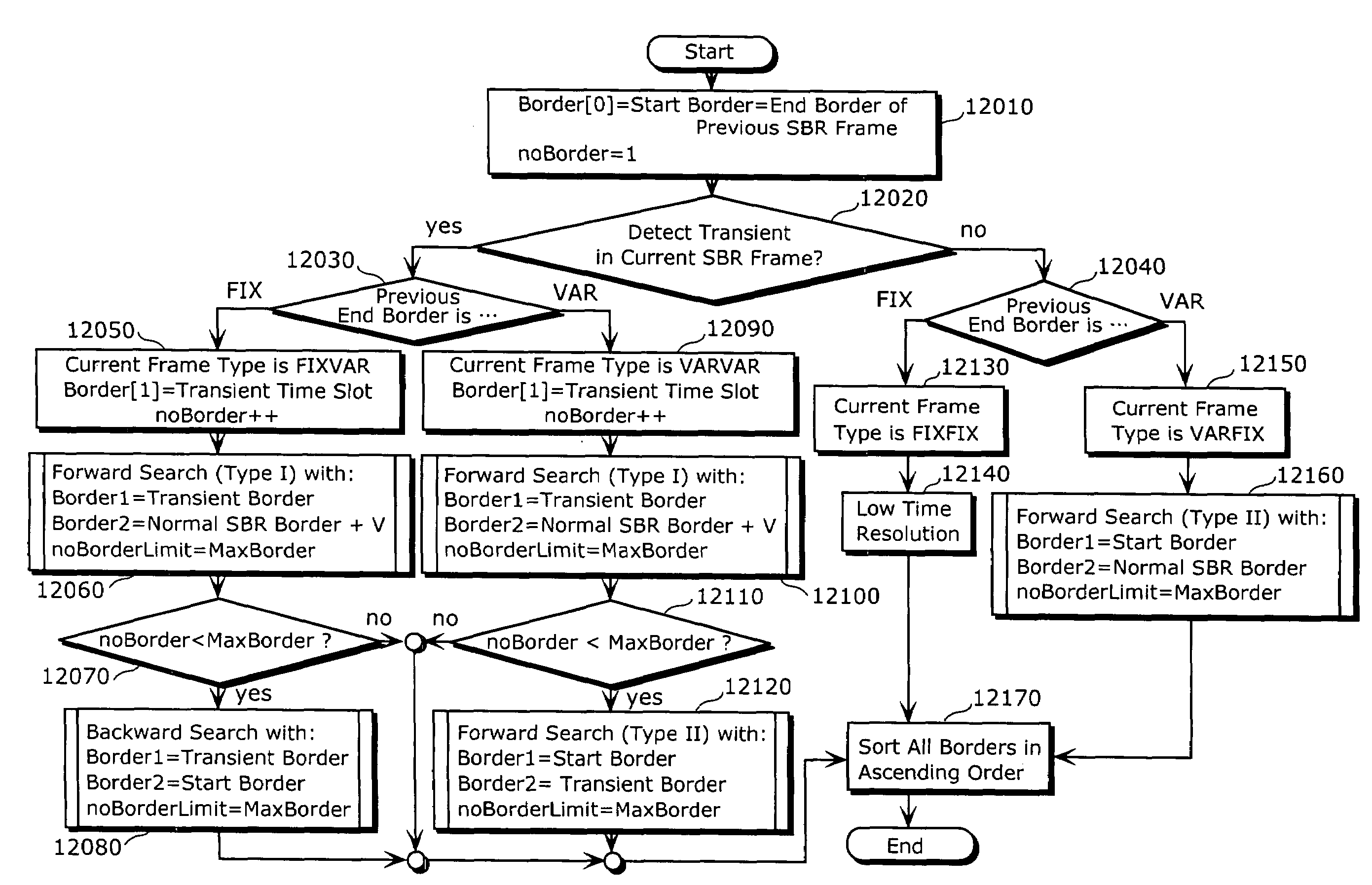
[0049]FIG. 13 is a diagram showing an overall flowchart of a time border determination unit of the present invention. FIG. 13 shows an overview of an overall time border determination operation. 12010 sets a first border ‘border[0]’ to the end border of the previous SBR frame. It also initializes a border counter ‘noBorder’ to 1. 12020 activates a transient detector for the current frame, to check for the most drastic transient behaviour from border[0] to (next nominal SBR border+V), where V is the amount of transgression into the next SBR frame allowed by the syntax.

[0050]If a transient is found,...


PUM


Abstract

A frame type for a current SBR frame is determined according to a type of end border of a previous frame, as well as presence of a transient in the current SBR frame. A start border is determined according to the end border of the previous SBR frame. For a FIXFIX frame, a low time-resolution setting is used. For a FIXVAR or a VARVAR frame, a search for intermediate borders is conducted in the region between the transient and maximum allowed end border location. The end border is also determined at this stage. If there is excess capacity for more borders, another search is conducted in the region between the transient and the start border. For a VARFIX frame, only one search needs to be conducted, in the whole region partitioned by a variable start border and a fixed end border. All of the above are accomplished with two Forward Search operations and one Backward Search operation. They employ the same principle, which is based on evaluating the signal variation of a time segment, but with minor variations to suit the scenarios in which they are applied.

Description

TECHNICAL FIELD[0001]The present invention relates to a systematic segmentation method for determining time borders and frequency resolution for bandwidth expansion technologies that employ a subband coding strategy, such as the Spectral Band Replication (SBR) technology. More specifically, the present invention relates to a method for dividing a signal frame into segments appropriate for the subband coding strategy, using time borders and frequency borders in the segment.BACKGROUND ART[0002]In the subband coding strategy employed in the spectral expansion technologies, such as the SBR technology, it is important to properly segment a signal frame both in a time direction and in a frequency direction in order to prevent a problem that low-energy areas are forced to share the same average energy value as the large-energy areas. This would in turn lead to erroneous amplification at a decoder, which is a common source of audible artifacts.[0003]An objective of audio coding is to transf...

Claims


Application Information

Patent Timeline
Patent Type & Authority Patents(United States)
IPC IPC(8): G10L21/04G10L19/025H04B1/66
CPCG10L19/025G10L21/038H04B1/667
Inventor CHONG, KOK SENGNEO, SUA HONGTANAKA, NAOYANORIMATSU, TAKESHI
Owner PANASONIC CORP
Why Eureka
Try Eureka