
Power savings apparatus and method for wireless network devices

a wireless network device and power saving technology, applied in the field of networks, can solve the problems of consuming power, consuming a significant amount of power, and remaining active, and achieve the effect of reducing current consumption

Active Publication Date: 2008-11-18
MARVELL ASIA PTE LTD
View PDF23 Cites 57 Cited by
  • Summary
  • Abstract
  • Description
  • Claims
  • Application Information

AI Technical Summary

Benefits of technology

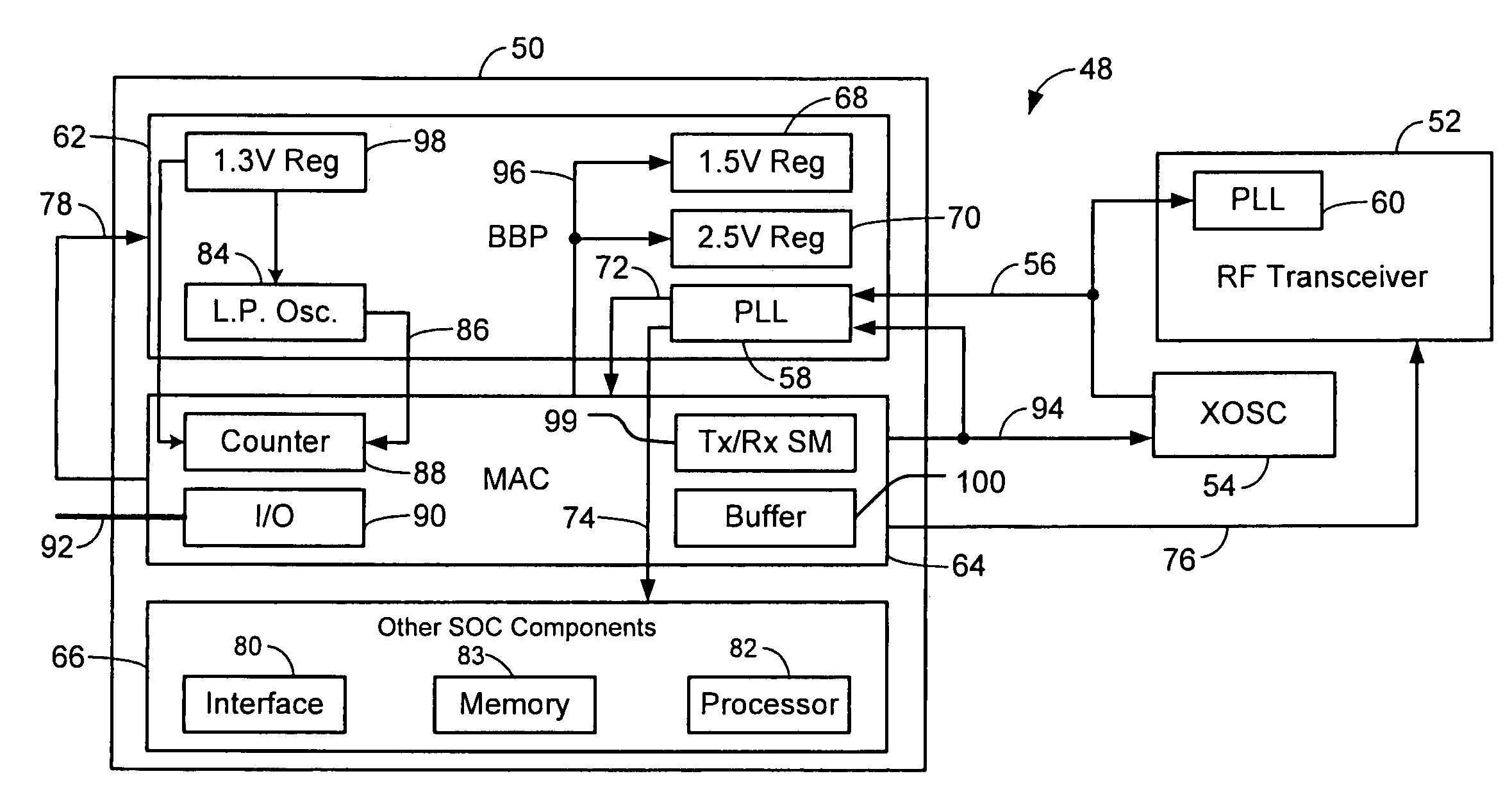
[0007]A wireless network device having active and inactive modes comprises a clock generating module that generates a first clock signal having a first clock rate. A voltage supply module generates a first voltage level and a second voltage level that is less than the first voltage level. A first digital module receives the first clock rate and the first voltage level during the active mode, receives the second voltage level during the inactive mode and does not receive the first clock signal during the inactive mode. A first analog module communicates with the voltage supply module and has reduced current consumption during the inactive mode.
[0008]In other features, the voltage supply module generates a third voltage level and the first analog module receives the third voltage level during the active mode. The first analog module reduces the current consumption during the inactive mode in response to a control signal. The first analog module receives the first voltage level during both the active and inactive modes. The first analog module reduces the current consumption during the inactive mode in response to a control signal.

Problems solved by technology

However, the voltage regulator in the BBP remains active during the low power mode and still consumes a significant amount of power from digital switching as well as leakage current when advanced deep sub-micron technology is used.
Additionally, the XOSC and PLL devices may remain active and also consume power during the low power mode.
However, many system components remain active during the low power mode and continue to consume power.
For example, the device may lower a frequency of operation so that calculations take longer to complete.
However, these system components still continue to consume power even when there are no computations to be performed.

Method used


Image

  • Power savings apparatus and method for wireless network devices
  • Power savings apparatus and method for wireless network devices
  • Power savings apparatus and method for wireless network devices

Examples


Embodiment Construction

[0045]The following description of the preferred embodiment(s) is merely exemplary in nature and is in no way intended to limit the invention, its application, or uses. For purposes of clarity, the same reference numbers will be used in the drawings to identify similar elements. As used herein, the term device refers to an application specific integrated circuit (ASIC), an electronic circuit, a processor (shared, dedicated, or group) and memory that execute one or more software or firmware programs, a combinational logic circuit, or other suitable components that provide the described functionality.

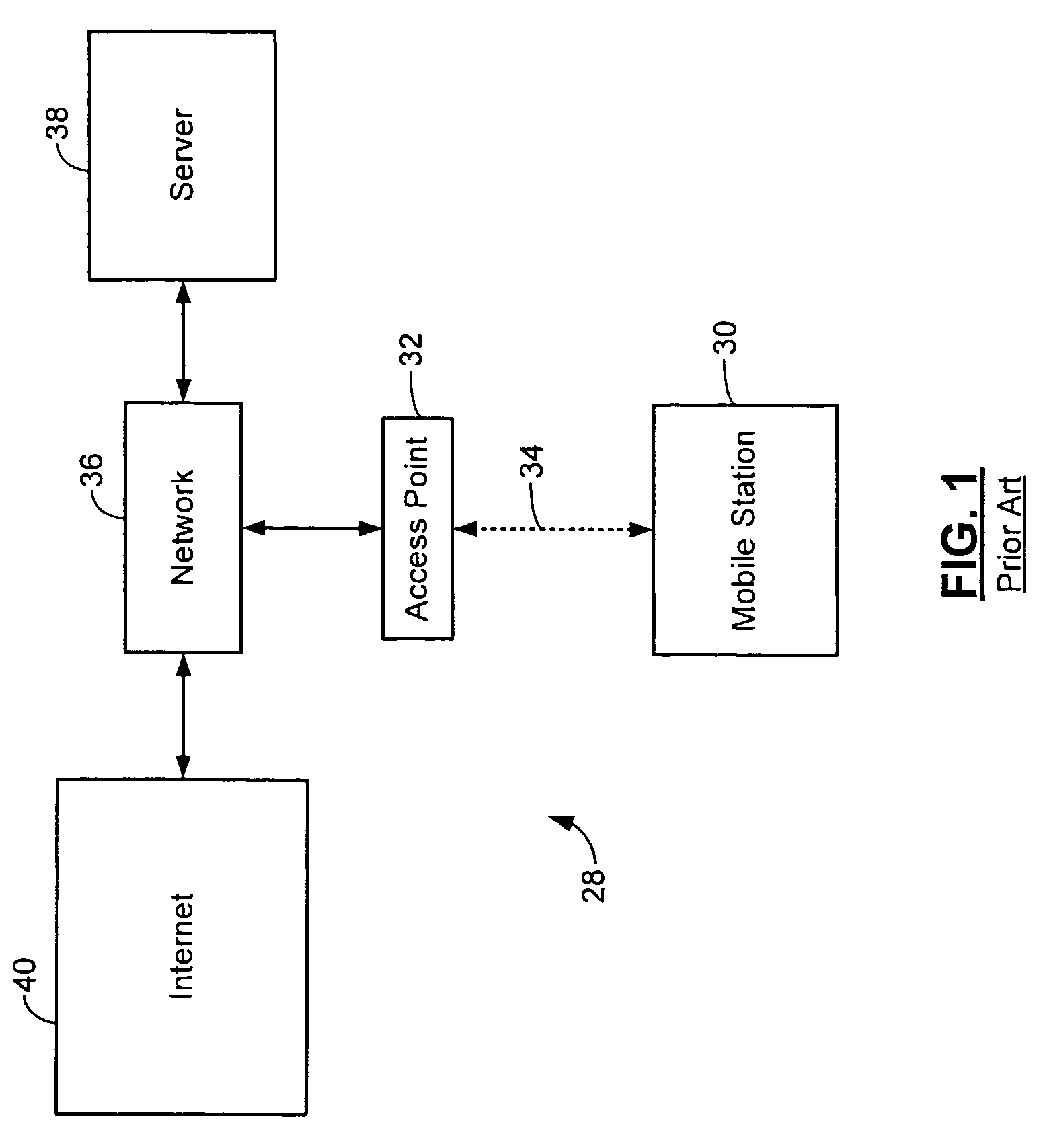
[0046]Referring to FIG. 1, a first wireless network 28 is illustrated in an infrastructure mode as defined by IEEE 802.11 and other future wireless standards. The first wireless network 28 includes one or more mobile stations 30 and one or more access points (AP) 32. The mobile station 30 and the AP 32 transmit and receive wireless signals 34. The AP 32 is a node in a network 36. The netw...


PUM


Abstract

A wireless network device having active and inactive modes comprises a clock generating module that generates a first clock signal having a first clock rate. A voltage supply module generates a first voltage level and a second voltage level that is less than the first voltage level. A first digital module receives the first clock rate and the first voltage level during the active mode, receives the second voltage level during the inactive mode and does not receive the first clock signal during the inactive mode. A first analog module communicates with the voltage supply module and has reduced current consumption during the inactive mode.

Description

CROSS-REFERENCE TO RELATED APPLICATIONS[0001]This application is a continuation-in-part of U.S. patent application Ser. No. 10 / 650,887 filed on Aug. 28, 2003. The disclosure of the above application is incorporated herein by reference in its entirety.FIELD OF THE INVENTION[0002]The present invention relates to networks, and more particularly to reducing power consumption of wireless network devices.BACKGROUND OF THE INVENTION[0003]IEEE section 802.11, which is hereby incorporated by reference in its entirety, defines several different standards for configuring wireless Ethernet networks and devices. For example, 802.11 standards that have been popularized include 802.11(a), 802.11(b) and 802.11(g). Wireless Ethernet network devices may be implemented by a system on chip (SOC) circuit that includes a baseband processor (BBP), a medium access controller (MAC) device, a host interface, and one or more processors. The SOC circuit may include a radio frequency (RF) transceiver or the RF ...

Claims


Application Information

Patent Timeline
Patent Type & Authority Patents(United States)
IPC IPC(8): G06F1/32
CPCH04W52/029Y02B60/50Y02D30/70
Inventor DONOVAN, TIMOTHYJAMAL, SHAFIQSONG, YONGHUACHUNG, CHIA-CHUNTRAN, TAMTSE, LAWRENCE
Owner MARVELL ASIA PTE LTD
Learn More