Method for mounting a surface lighting system and surface lighting system

a technology of surface lighting and mounting system, which is applied in the direction of lighting and heating apparatus, instruments, heat measurement, etc., can solve the problem that the assembly concept of the surface lighting system is not disclosed in the documentation, and achieves the effect of facilitating the reduction to practice the method, reducing the number of electronic components, and high light outpu

Inactive Publication Date: 2008-12-02
OSRAM OPTO SEMICONDUCTORS GMBH
View PDF16 Cites 44 Cited by
  • Summary
  • Abstract
  • Description
  • Claims
  • Application Information

AI Technical Summary

Benefits of technology

[0022]This has the advantage of minimizing the number of electronic components needed to drive the primary radiation sources. Furthermore, it eliminates the need for electrical connection sites between the individual flexible carriers.
[0023]In a further preferred embodiment of the method, structures are created on the rigid carrier for use in bending the mounting area of the flexible carrier out of the reference plane into the desired position when the flexible carrier is placed on the rigid carrier. This embodiment of the method has advantages from a process engineering standpoint and thereby facilitates the reduction to practice of the method.
[0024]In a further preferred embodiment of the method, a light-emitting diode (“LED” for short) component is used as the primary radiation source. These devices offer the advantage of high light output together with compact construction and low weight.
[0025]In a further embodiment of the inventive method, at least two light guides are used and are advantageously connected in adjacent edge regions by means of an optical coupling medium. Suitable for use as the optical coupling medium are materials having similar optical properties to the material of the light guide. In this way, radiation can pass from one light guide into the adjacent one with as little hindrance as possible, thus improving the radiation characteristic of the surface illumination system. If the edge regions of adjacent light guides are potted or glued, this can further contribute to the mechanical stability of the surface illumination system.
[0026]In a further preferred embodiment of the method, at least one radiation transparent film is applied to the radiation emitting front side of the light guide. This also helps to improve the mechanical stability of the light guide combination.

Problems solved by technology

However, the documents do not disclose any assembly concepts for making surface illumination systems of this kind.

Method used


Image

  • Method for mounting a surface lighting system and surface lighting system
  • Method for mounting a surface lighting system and surface lighting system
  • Method for mounting a surface lighting system and surface lighting system

Examples


Embodiment Construction

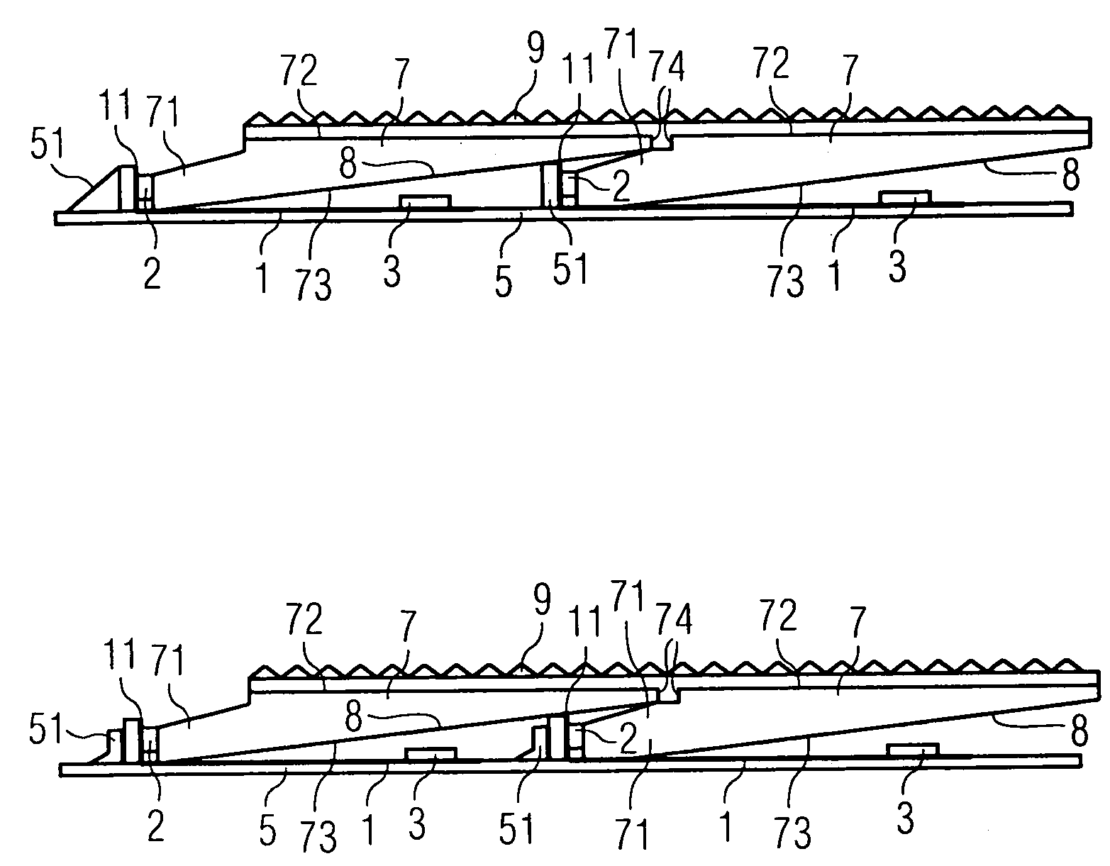
[0047]In the exemplary embodiments and figures, elements of the same kind or identically acting elements are provided with the same respective reference numerals. The illustrated elements in the figures should not be considered true to scale. Rather, they may be depicted as exaggeratedly large to provide a better understanding.

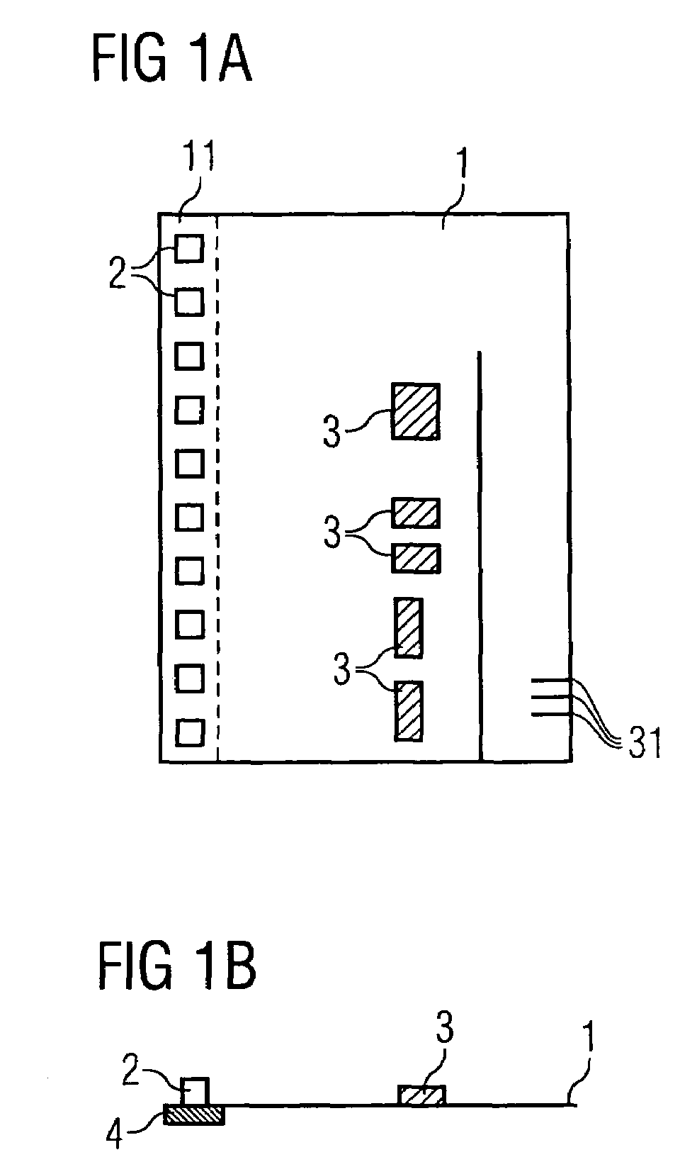
[0048]According to a first exemplary embodiment (see FIG. 1a) of the method, primary radiation sources 2, for example LEDs, are attached in a row to the edge of a flexible printed circuit board 1 and are electrically contacted by means of electrical conductive traces. In addition, further electronic components 3, such as for example driver modules for driving the LEDs 2, are attached to the flexible printed circuit board 1 and connection sites 31 for electrical contacting are formed laterally. Cooling bodies 4 (see FIG. 1b) are mounted on the side of the flexible printed circuit board 1 opposite from the LEDs 2, to dissipate the waste heat developed when the L...


PUM

PropertyMeasurementUnit
refractive indexaaaaaaaaaa
flexibleaaaaaaaaaa
radiation-transparentaaaaaaaaaa

Abstract

In a method of assembling a surface illumination system having an electromagnetic radiation emitting front side, at least one primary radiation source suitable for emitting electromagnetic radiation when operating is disposed on at least one mounting area of a flexible carrier. The flexible carrier has a front side and a back side opposite said front side, the front side of the flexible carrier defines a reference plane. The mounting area of the flexible carrier on which the primary radiation source is disposed is then bent out of the reference plane such that an optical axis of the primary radiation source extends parallel or obliquely to the reference plane. In a further step, at least one light-conducting guide having a radiation emitting front side and at least one incoupling region is disposed on the flexible printed circuit board so that in operation, the primary radiation source emits radiation into the incoupling region of the light guide and the radiation emitting front side of the light guide points in the direction of the radiation emitting front side of the surface illumination system. A corresponding surface illumination system is also described.

Description

CROSS-REFERENCE TO RELATED APPLICATIONS[0001]This application is the National Stage of International Application No. PCT / DE2005 / 000875, filed on May 12, 2005, which claims the priority to German Patent Applications Ser. No. 10 2004025414.1, filed on May 24, 2004 and Ser. No. 102004046696.3, filed on Sep. 24, 2004. The contents of all applications are hereby incorporated by reference in their entireties.FIELD OF THE INVENTION[0002]The invention relates to a method of assembling a surface illumination system and a surface illumination system.BACKGROUND OF THE INVENTION[0003]Surface illumination systems have a wide variety of applications. They can, for example, serve as illuminants in lamps or design systems. In particular, surface illumination systems can be used to backlight displays such as liquid crystal displays (LCDs).[0004]Known from U.S. Pat. No. 6,646,367 B2 and U.S. Pat. No. 6,241,358 B1, for example, are surface illumination systems that can be constructed in cascade form f...

Claims


Application Information

Patent Timeline
Patent Type & Authority Patents(United States)
IPC IPC(8): F21V7/04G02F1/00F21V8/00G02B6/00G02B6/42G02F1/13357H01L33/00H01L33/48H01L33/60
CPCG02B6/0046G02B6/008G02B6/0053G02B6/0068G02B6/0083G02B6/0085G02B6/42G02B6/0001
Inventor LANG, KURT-JURGENOTT, HUBERTPLOTZ, LUDWIGPOH, CHRISTIANWANNINGER, MARIO
Owner OSRAM OPTO SEMICONDUCTORS GMBH
Why Eureka
Try Eureka