
Intraoperative joint force measuring device, system and method

a technology of joint force and measurement device, applied in the field of surgical systems for measuring joint load, can solve the problems of affecting the optimal soft tissue tension of patients, reducing the efficiency of the patient's rehabilitation, so as to achieve optimal implant placement and size, and reduce the risk of femoral cavity injury

Active Publication Date: 2008-12-02
UNIV OF FLORIDA RES FOUNDATION INC
View PDF38 Cites 41 Cited by
  • Summary
  • Abstract
  • Description
  • Claims
  • Application Information

AI Technical Summary

Benefits of technology

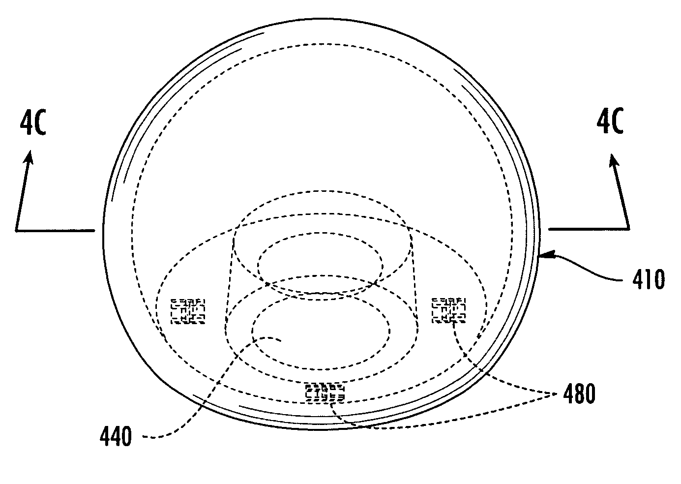
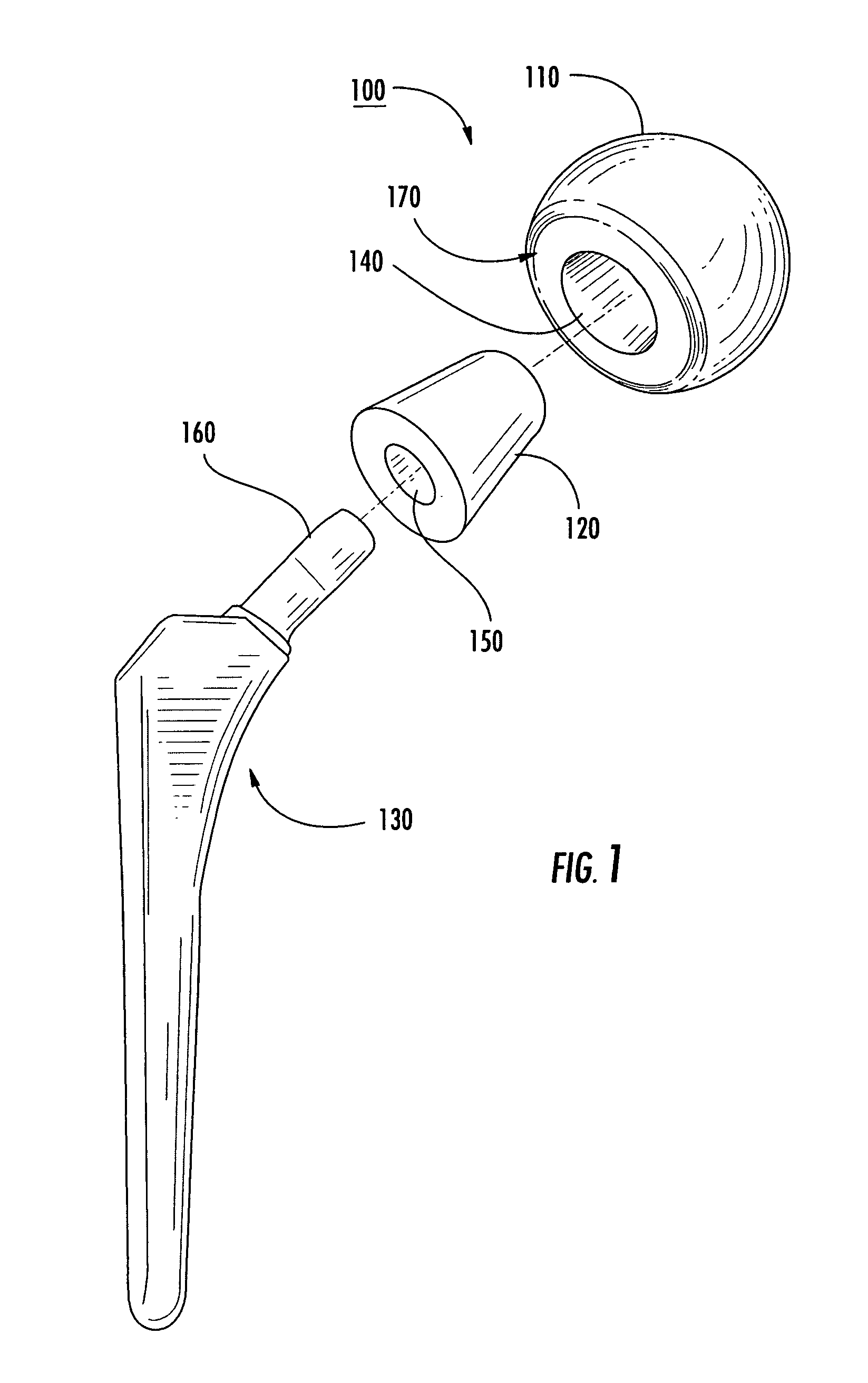
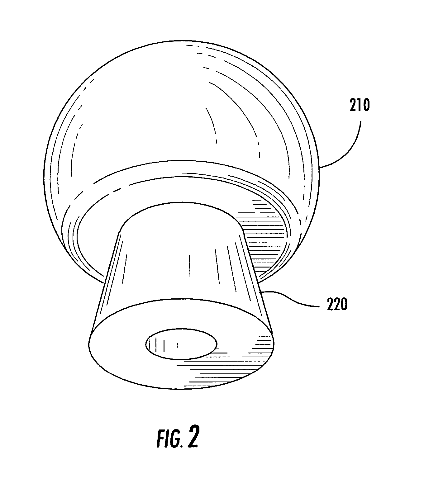
The present invention provides an intraoperative joint head with a stem attachment structure that can be removably attachable to a stem, allowing surgeons to measure joint forces during surgery. The device includes a force sensor housed by the joint head for measuring in vivo forces, which can be used to adjust implants and prosthetics. The stem attachment structure can be removably insertable in the joint head and can provide unique dimensions relative to the joint heads in the series. The stem attachment structure can also include one or more of a recess for receiving the stem, stem attachment tool, and stem attachment structure that can be adjusted based on the measured joint forces. The kit can also include an anatomical tracking system for tracking movements of body parts. The system can provide calculations from in vivo joint reaction forces and vectors. Overall, the invention allows for quantitative adjustments to implants and prosthetics during joint replacement surgery.

Problems solved by technology

In the event of surgery affecting the joint, soft tissue tension is often affected; however, optimal soft tissue tension is not always returned to patient.
The removal of the femoral head allows the two points of attachment of the abductor muscle to come together and results in a loss of tension in the abductor muscle.
Especially, osteoarthritis secondary to developmental dysplasia of the hip can present numerous technical challenges to a THA procedure, including altered femoral anatomy, limb length discrepancy, and soft tissue contractures.
After the procedure, problems can arise with implants, including aseptic loosening, polyethylene wear, and dislocation.
Dislocation after THA can cause discomfort, inconvenience and expense.
Devices created for such testing do not consider or take into effect the combined stresses experienced by the hip components during life.
The devices used in such research are not capable of measuring forces from a variety of different load applications, as truly experienced by the hip of an ambulatory person or even the soft tissue tension through a complete range of motion.
Importantly, such devices, and the testing situations in which they are arranged, are not designed to take into account the effects and properties of live soft tissues, which have significantly different elastic properties in comparison to dead soft tissues.
Finally, these devices and the artificial testing situations in which they are used to develop models, cannot possibly take into account the unique anatomical considerations presented by the individual patient.
Further, intraoperative procedures for measuring forces experienced by the implant and at the hip are non-existent because devices for measuring such forces do not exist.
Further, providing multiple intraoperative components that are removably attachable allows for components of various dimensions to be tested without subjecting the patient to potentially damaging implanting, such as seating multiple femoral implants by hammering them into the femoral cavity and risking femoral cavity injury, and removing of multiple test components that are integrated and do not provide attachable and detachable components.

Method used


Image

  • Intraoperative joint force measuring device, system and method
  • Intraoperative joint force measuring device, system and method
  • Intraoperative joint force measuring device, system and method

Examples


Embodiment Construction

[0029]The present invention provides an intraoperative device, kit, method and system for measuring joint forces experienced by implants so that surgeons can quantify needed adjustments for implants and prosthetics. In contrast to the prior art, with the device, kit, method and system, surgeons can measure joint forces, such as soft tissue tension, intraoperatively, make adjustments based on measurements instead of subjective observation, and provide optimal implant placement and size. Importantly, the intraoperative device not only allows the surgeon to obtain quantitative soft tissue tension measurements that are unique to the patient due to unique anatomical size and shape, the detachable arrangement of the device allows the surgeon to obtain soft tissue tension measurements for a variety of different implant sizes and arrangements. Such a removably attachable device can allow the surgeon to select the optimal implant size and arrangement based on quantitative measurements withou...


PUM


Abstract

A surgical device for joint replacement surgery includes an intraoperative joint head having a stem attachment structure where the stem attachment structure may be removably attachable to a stem and a force sensor housed by the joint head for measuring in vivo forces during surgery. The in vivo forces may be generated by one or more of tension provided by soft tissue, load application during surgery, limb movement during surgery, and a combination thereof. Also, the joint head may provide a cavity where the stem attachment structure houses the force sensor and may be removably insertable in the joint head cavity. A method of performing joint replacement surgery includes installing an intraoperative joint head having a force sensor housed by the joint head and a stem attachment structure, the stem attachment structure being removably attachable to a stem, measuring joint forces, and adjusting an implant parameter based on the measured joint forces.

Description

CROSS-REFERENCE TO RELATED APPLICATIONS[0001]Not applicable.FIELD OF THE INVENTION[0002]The present invention relates to surgical systems, devices and methods, and more particularly, to surgical systems for measuring joint loads during surgery.BACKGROUND OF THE INVENTION[0003]Joints are maintained in a secure position in the body via tension provided by soft tissues, such as muscles, tendons, and ligaments. For example, one soft tissue that secures the hip joint is the abductor muscle. The abductor muscle attaches to the pelvic bone at one end and to the femur on the other end and is tensed. In the event of surgery affecting the joint, soft tissue tension is often affected; however, optimal soft tissue tension is not always returned to patient.[0004]Total hip replacement or arthroplasty (“THA”) operations have become increasingly common in the United States, with more than 200,000 such operations occurring annually. A THA procedure can replace portions of the femur and the acetabulu...

Claims


Application Information

Patent Timeline
Patent Type & Authority Patents(United States)
IPC IPC(8): A61F2/32A61B5/00A61B5/103A61F2/36
CPCA61B5/6846A61B19/46A61F2/3609A61F2/4637A61F2/4657A61F2/4684A61B19/0271A61B2019/0278A61B2019/464A61F2/36A61F2/3662A61F2/468A61F2002/3021A61F2002/30299A61F2002/30332A61F2002/30344A61F2002/30354A61F2002/30405A61F2002/30448A61F2002/30507A61F2002/30604A61F2002/30616A61F2002/3067A61F2002/30716A61F2002/3611A61F2002/3619A61F2002/3625A61F2002/365A61F2002/4018A61F2002/4632A61F2002/4633A61F2002/4641A61F2002/4666A61F2002/4681A61F2220/0025A61F2220/0033A61F2220/005A61F2230/0067A61F2230/0093A61F2250/0002A61F2250/0064A61F2250/009A61F2310/00017A61F2310/00023A61F2310/00029A61F2310/00179A61F2002/30339A61F2002/30593A61B50/33A61B90/06A61B2050/3008A61B2090/064
Inventor BANKS, SCOTT A.TANINO, HIROMASA
Owner UNIV OF FLORIDA RES FOUNDATION INC
Learn More