Tuning circuit

a technology of tuning circuit and filter, applied in the field of filters, to achieve the effect of maximizing the effect of tuning

Inactive Publication Date: 2008-12-09
INTEGRANT TECH
View PDF8 Cites 11 Cited by
  • Summary
  • Abstract
  • Description
  • Claims
  • Application Information

AI Technical Summary

Benefits of technology

[0022]The present invention has been also made in an effort to provide a tuning circuit having advantages of maximizing an effect of tuning by performing tuning at a period of a clock unrelated to an external change.

Problems solved by technology

However, the related art method has the following problems.

Method used


Image

  • Tuning circuit
  • Tuning circuit
  • Tuning circuit

Examples


Embodiment Construction

[0051]The preferred embodiment of the present invention will be described in detail with reference to the accompanying drawings.

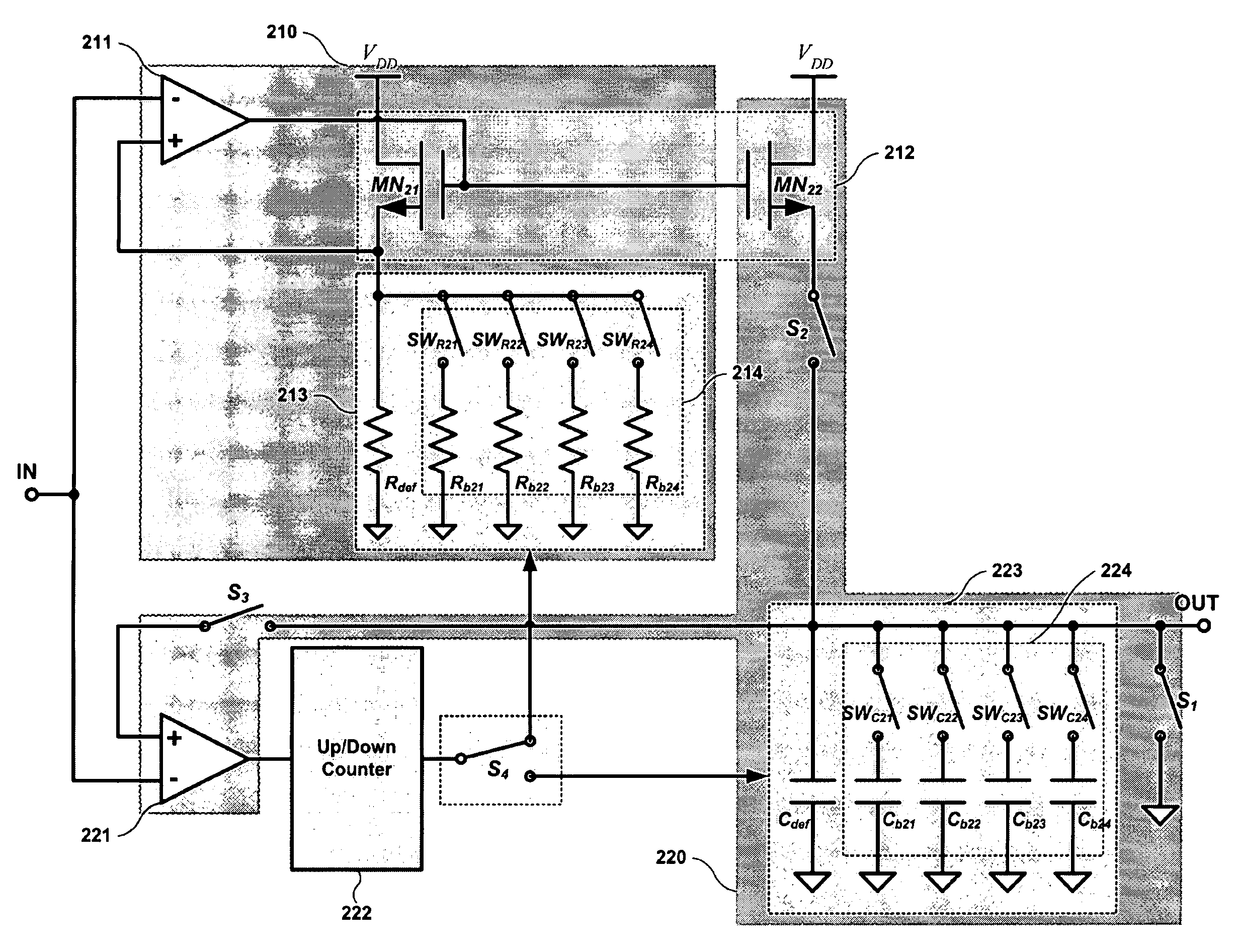
[0052]FIG. 2a is a circuit diagram showing a tuning circuit according to one embodiment of the present invention.

[0053]As shown in FIG. 2a, the tuning circuit comprises a current generation unit 210, a capacitance correction unit 220, an up-down counter 222, and a selection unit S4.

[0054]

[0055]A current generation unit 210 comprises a first comparator 211, a first transistor MN21 and a resistor unit 213.

[0056]Herein, the resistor unit 213 comprises a basic resistor (Rdef) and a switch-resistor bank 214.

[0057]Herein, in the switch-resistor bank 214, one or more switch-resistor structures, in which resistor Rb21˜Rb24 and switch SWR21˜SWR24 are connected in series, are connected in parallel.

[0058]The capacitance correction unit 220 comprises a second comparator 221, a second transistor MN22, a capacitor unit 223, a first switch S1, a second switch S2 and a thi...


PUM


Abstract

The present invention relates to a filter and, more particularly, to a tuning circuit of a filter for correcting a cut-off frequency of the filter. The tuning circuit comprises a current generation unit having a first transistor and a variable resistor unit, and a capacitance correction unit having a second transistor, a capacitor unit, an up-down counter and a selection unit for selecting a control path of the up-down counter for varying the resistance or capacitance.

Description

[0001]This Nonprovisional application claims priority under 35 U.S.C. § 119(a) on Patent Application No. 10-2005-0053760 filed in Korea on Jun. 22, 2005, the entire contents of which are hereby incorporated by reference.BACKGROUND OF THE INVENTION[0002]1. Field of the Invention[0003]The present invention relates to a filter and, more particularly, to a tuning circuit of a filter for correcting a cut-off frequency of the filter.[0004]2. Description of the Related Art[0005]FIG. 1a shows a related art tuning circuit.[0006]The tuning circuit as shown in FIG. 1a is disclosed in a U.S. Patent Laid Open Publication No. US 2004 / 0169565.[0007]As shown in FIG. 1a, the tuning circuit comprises a filter unit 110, a comparator 120, and a controller unit 130.[0008]The filter unit 110 comprises a first RC unit 111a, a second RC unit 111b, switches SW1a, SW1b, SW2a, and SW2b for charging and discharging the first and second RC units 111a and 111b, and a capacitor array 112 for controlling capacitan...

Claims


Application Information

Patent Timeline
Patent Type & Authority Patents(United States)
IPC IPC(8): H03K5/00
CPCH03H7/0153H03H11/1291H03H2210/021H03H2210/043H03J3/08H03J7/00
Inventor KIM, SEYEOBJEONG, MINSU
Owner INTEGRANT TECH
Why Eureka
Try Eureka