Direct injection gaseous-fuelled engine and method of controlling fuel injection pressure

a gaseous-fuelled engine and gaseous-fuelled technology, which is applied in the direction of braking systems, process and machine control, instruments, etc., can solve the problems of inability to recirculate any high-pressure gas back to the storage vessel, introduce too much heat to the liquefied fuel, etc., to improve fuel efficiency, reduce engine emissions, and improve combustion characteristics

Active Publication Date: 2008-12-09
WESTPORT FUEL SYST CANADA INC
View PDF19 Cites 65 Cited by
  • Summary
  • Abstract
  • Description
  • Claims
  • Application Information

AI Technical Summary

Benefits of technology

[0025]In another preferred embodiment, the method further comprises injecting a pilot fuel into the combustion chamber to trigger ignition of the gaseous fuel. In such embodiments, to reduce the modifications required to a conventional engine's cylinder head, a single fuel injection valve can be operable to introduce both the pilot fuel and the gaseous fuel into the combustion chamber. With pilot fuel and gaseous fuel fluidly isolated from each other in the fuel injection valve to allow separate and independent injection of the two fuels into the combustion chamber, it is preferable to regulate gaseous fuel pressure and pilot fuel pressure to reduce a pressure differential between the gaseous fuel and the pilot fuel before each of the fuels is delivered to the fuel injection valve. Gaseous fuel pressure is preferably negatively biased with respect to pilot fuel pressure, to prevent gaseous fuel from leaking into the pilot fuel or into liquid seals charged with liquid pilot fuel.
[0044]Accordingly, with the disclosed method and apparatus for controlling fuel injection pressure in a gaseous-fuelled engine with direct fuel injection, it is possible to improve combustion characteristics, improve fuel efficiency, and reduce engine emissions of NOx.

Problems solved by technology

This is because it is not practical to recirculate any of the high-pressure gas back to the storage vessel.
In a cryogenic system, this would introduce too much heat to the liquefied fuel.

Method used


Image

  • Direct injection gaseous-fuelled engine and method of controlling fuel injection pressure
  • Direct injection gaseous-fuelled engine and method of controlling fuel injection pressure
  • Direct injection gaseous-fuelled engine and method of controlling fuel injection pressure

Examples


Embodiment Construction

)

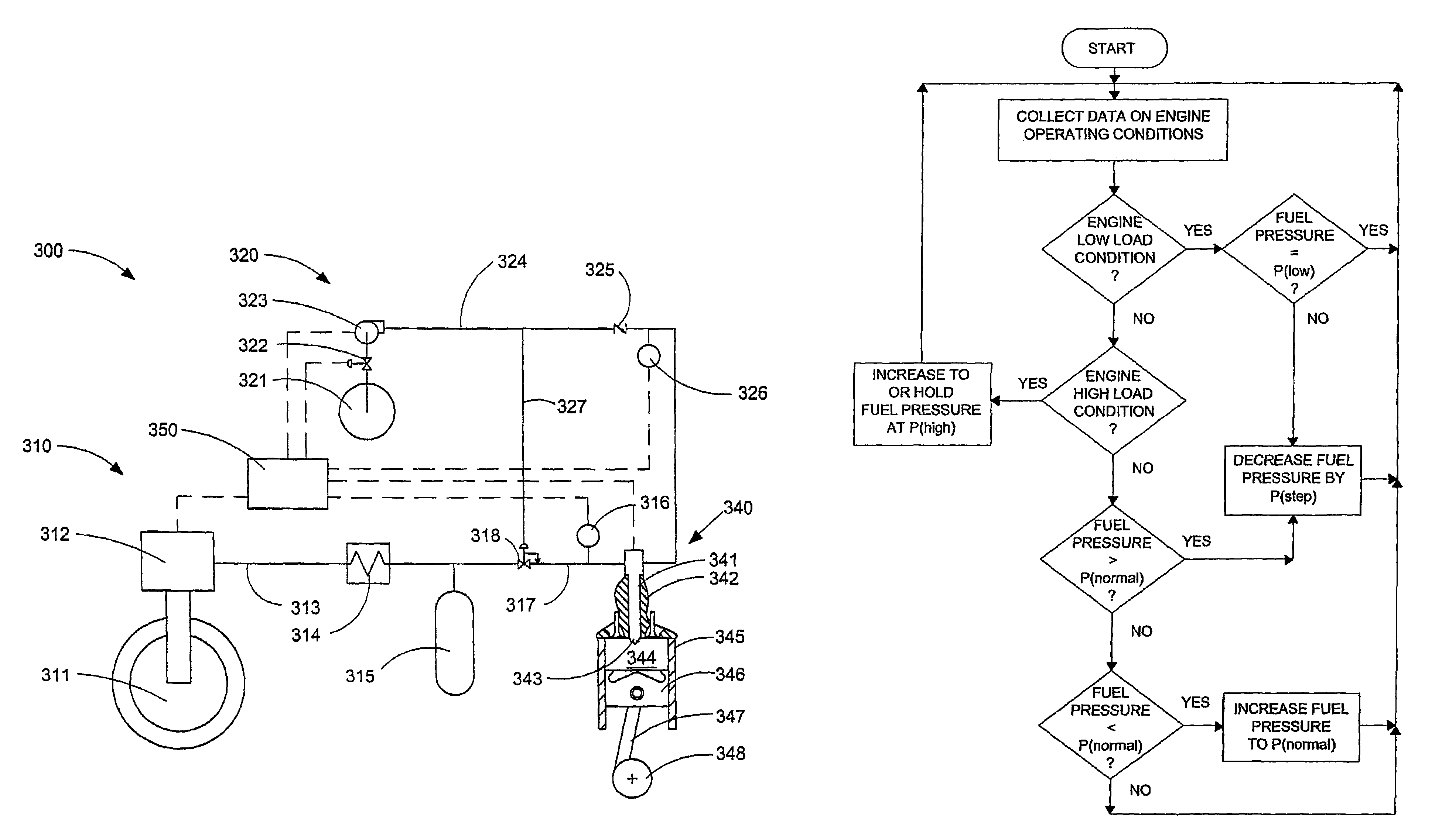
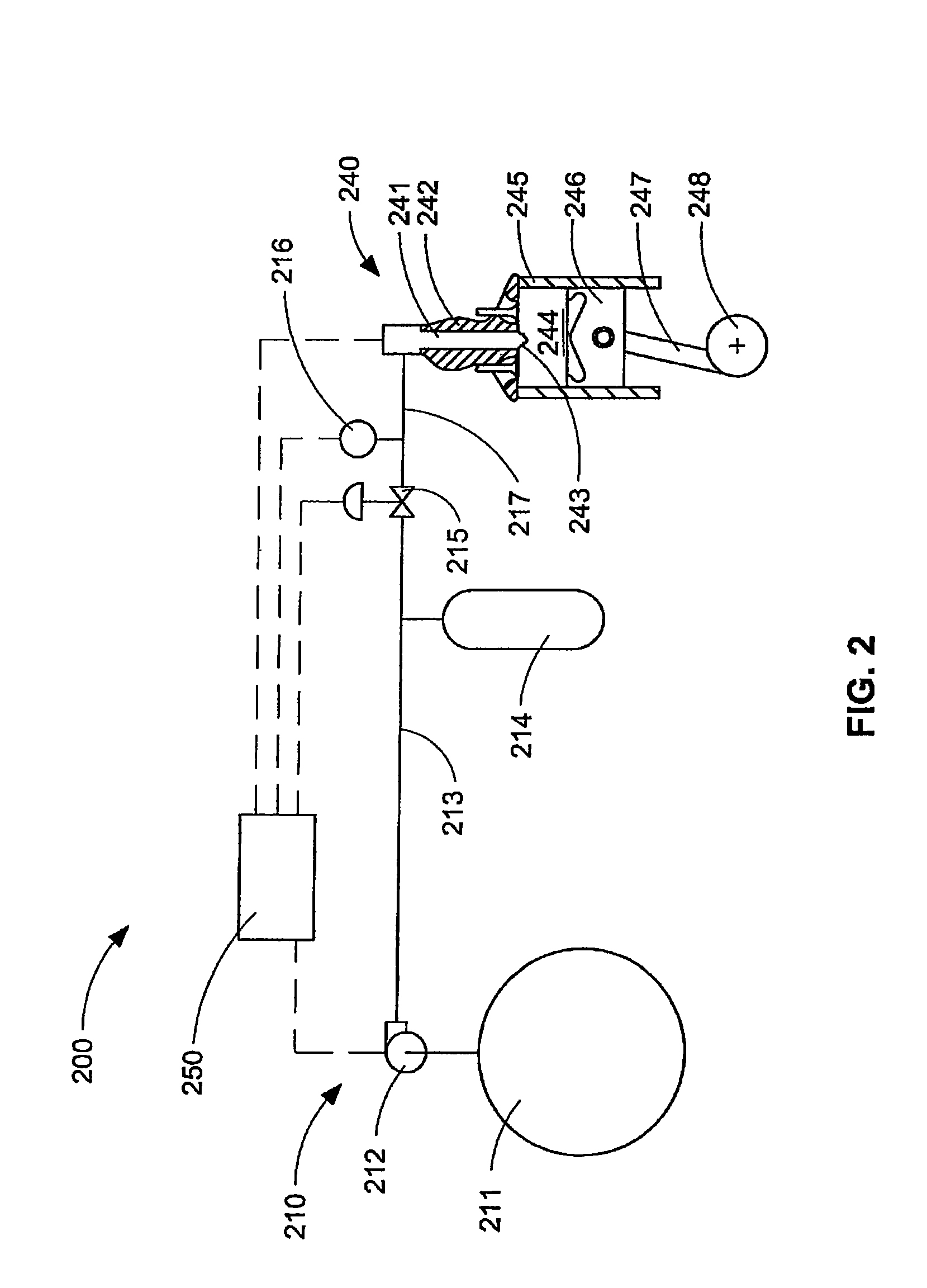
[0051]FIGS. 2 and 3 show schematic views of two arrangements for a gaseous-fuelled internal combustion engine system.

[0052]Referring to FIG. 2, internal combustion engine system 200 illustrates an embodiment that stores the gaseous fuel as compressed gas. Internal combustion engine system 200 generally comprises fuel delivery subsystem 210, fuel injection subsystem 240, and engine controller 250. Each of these subsystems is described in more detail below as well as a description of the manner in which they cooperate with each other to introduce a gaseous fuel into a combustion chamber where it can be combusted.

[0053]Because gaseous fuels typically do not auto-ignite at the same temperature and pressure as conventional liquid fuels such as diesel fuel, to preserve the general configuration of conventional diesel engines, including the compression ratio, an ignition assist device can be provided to assist with ignition of gaseous fuels. For example, an ignition assist device can be a...


PUM


Abstract

An engine operating method and a direct injection gaseous fuelled system directly injects a gaseous fuel into a combustion chamber during a compression stroke, commands gaseous fuel injection pressure to a target value that is determined as a function of at least one pre-selected engine parameter, measures actual gaseous fuel injection pressure and adjusts fuel injection pulsewidth to correct for differences between the target value and the actual gaseous fuel injection pressure to thereby inject the desired mass quantity of gaseous fuel as determined from an engine map.

Description

CROSS-REFERENCE TO RELATED APPLICATION(S)[0001]This application is a continuation of International Application No. PCT / CA2006 / 000828, having an international filing date of May 18, 2006, entitled “Direct Injection Gaseous-Fuelled Engine and Method of Controlling Fuel Injection Pressure”. International Application No. PCT / CA2006 / 000828 claimed priority benefits, in turn, from Canadian Patent Application No. 2,505,455 filed May 18, 2005, and U.S. Provisional Patent Application Ser. No. 60 / 682,629, also filed May 18, 2005. International Application No. PCT / CA2006 / 000828 is hereby incorporated by reference herein in its entirety.FIELD OF THE INVENTION[0002]The present invention relates to an engine with gaseous fuel introduced by direct injection into the combustion chamber(s) and an operating method for controlling gaseous fuel injection pressure responsive to predetermined operating conditions for such an engine.BACKGROUND OF THE INVENTION[0003]So-called compression ignition engines e...

Claims


Application Information

Patent Timeline
Patent Type & Authority Patents(United States)
IPC IPC(8): F02M51/00F02B43/00G06F19/00F02D19/02F02M21/02
CPCF02D19/10F02D19/066F02M21/0245F02M21/0275F02D19/022F02D19/024Y02T10/36Y02T10/32F02M21/0215F02M21/0224Y02T10/30
Inventor ANCIMER, RICHARDBATENBURG, GREGTHOMPSON, JEFF
Owner WESTPORT FUEL SYST CANADA INC
Why Eureka
Try Eureka