Viscous material application apparatus

Inactive Publication Date: 2008-12-16
PANASONIC CORP
View PDF24 Cites 7 Cited by
  • Summary
  • Abstract
  • Description
  • Claims
  • Application Information

AI Technical Summary

Benefits of technology

[0024]Moreover in another suitable configuration, the temperature of the

Problems solved by technology

However, in a viscous material application apparatus of the conventional configuration described above, because the compressed air supplied from the pressure regulating section 22 is applied on top of the viscous material 5 contained in the material supply section 1, then depending on the characteristics of the viscous material 5, the pressure of the compressed air may be affected by the viscosity resistance of the viscous material 5 and find it difficult to reach the vicinity of the distant discharge port 4a of the disch

Method used


Image

  • Viscous material application apparatus
  • Viscous material application apparatus
  • Viscous material application apparatus

Examples


first embodiment

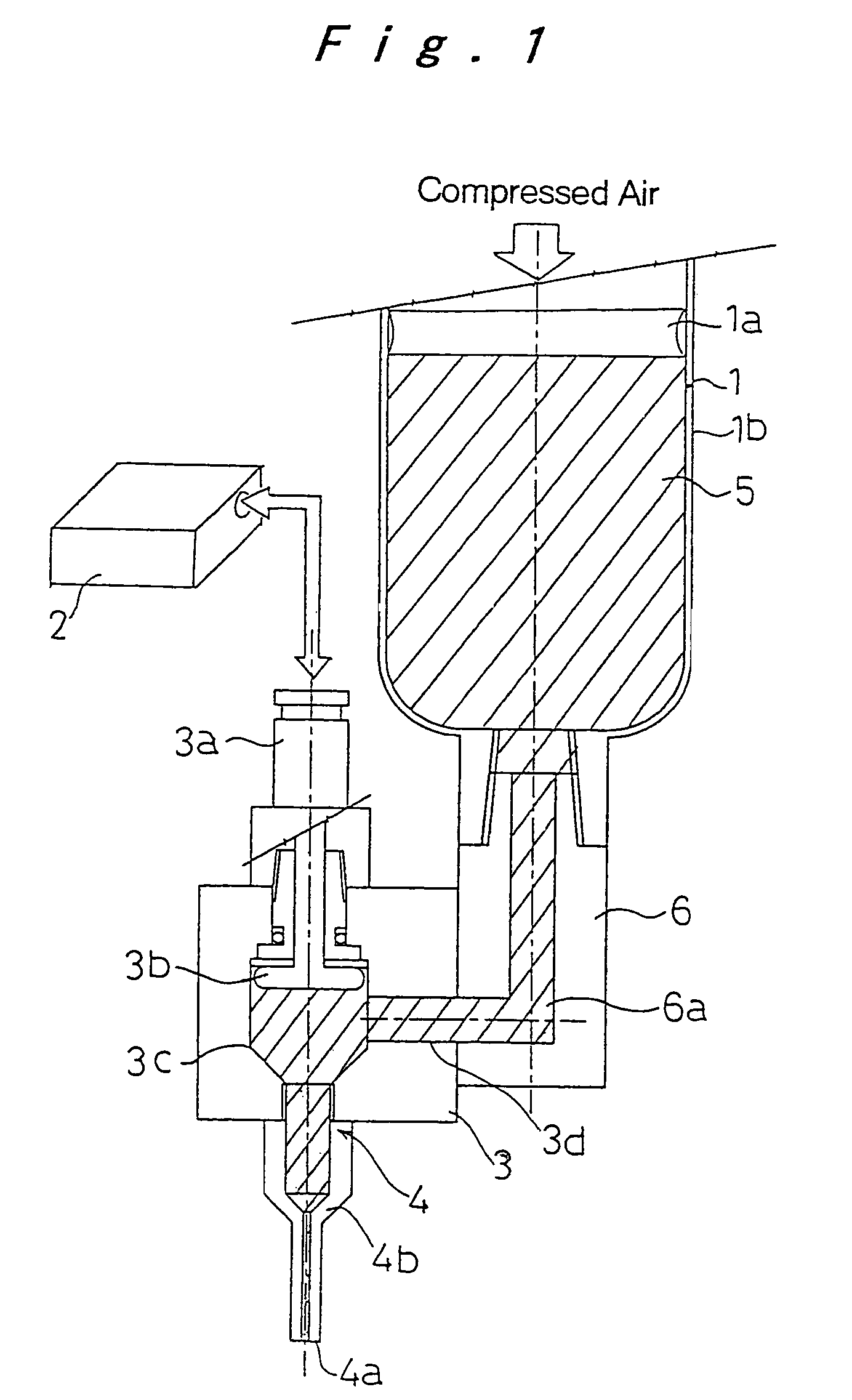
[0059]A viscous material application apparatus shown in FIG. 1 comprises a material supply section 1, an air supply section 2, and an application unit 3 which forms a main body of the apparatus. The material supply section 1 contains a viscous material 5 such as an adhesive and cream solder stored inside a cylinder shaped storage tank 1b, and under the effect of compressed air used for material supply, a plunger 1a operates and pressurizes the viscous material 5, and transfers the viscous material under pressure so that the inside of a chamber (pressurized chamber) 3c of the application unit 3 is always full.

[0060]The application unit 3 and the material supply section 1 are connected by a joint 6, and by positioning a through aperture 6a provided in the joint 6 so that the through aperture 6a interconnects with a viscous material supply passage 3d provided horizontally in the side of the aforementioned chamber 3c, the viscous material 5 is supplied to the inside of the application ...

second embodiment

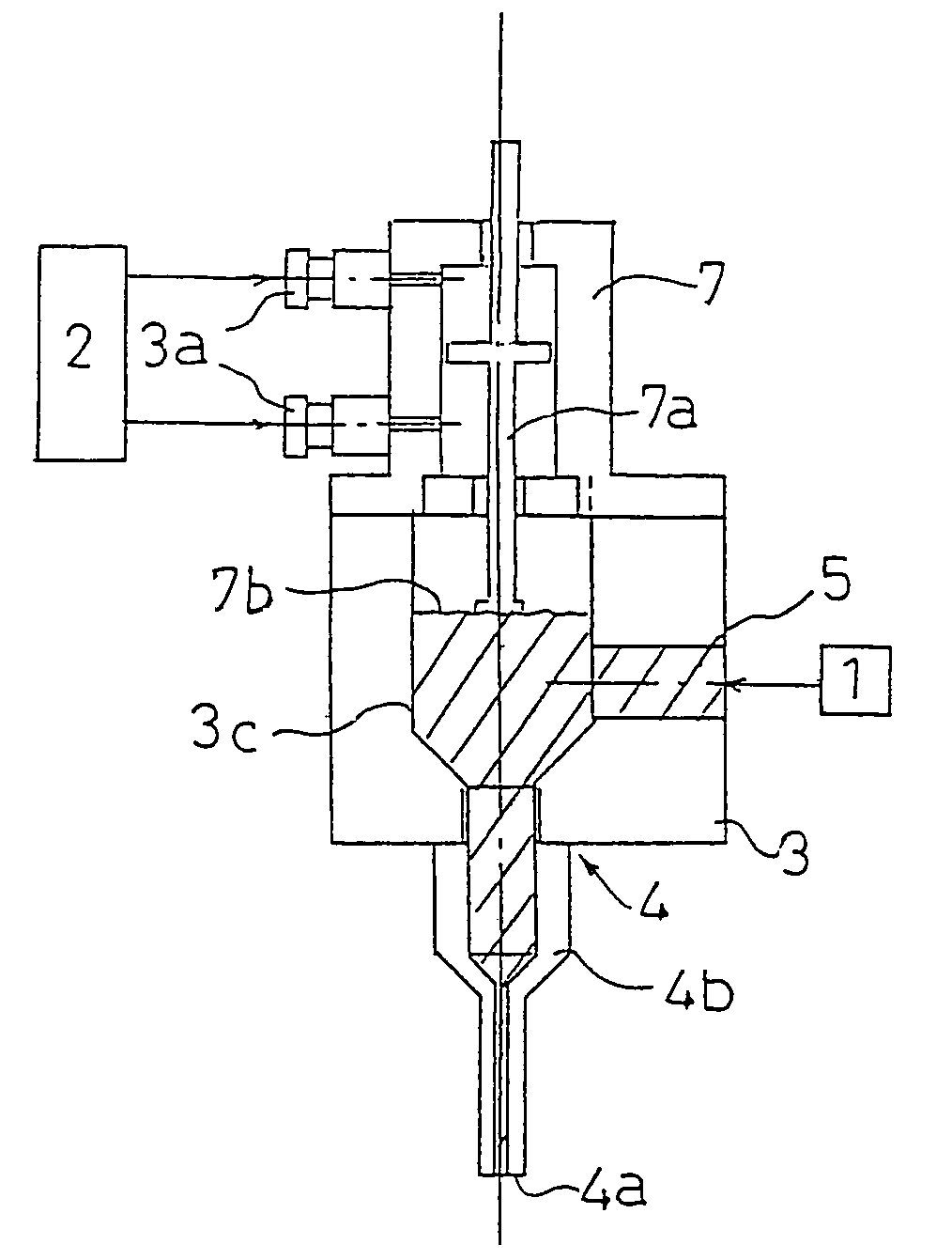
[0065] shown in FIG. 3, an air cylinder 7 which is connected to the air supply section 2 and a diaphragm 7b which is described below are used instead of the aforementioned discharge pressure regulating air pouch 3b. A piston 7a is provided in the air cylinder 7, and compressed air from the air supply section 2 which has been adjusted to a predetermined air pressure is supplied from an air port 3a, and accordingly the piston 7a moves up and down causing a deformation of the diaphragm 7b attached to the bottom end of the piston. This deformation of the diaphragm 7b causes an increase or a decrease in the capacity inside the chamber 3c, thereby applying pressure to, or releasing pressure from the viscous material 5. In addition to the device shown in the Figure, the diaphragm 7b may also utilize a bellows or the like.

[0066]According to a third embodiment shown in FIG. 4, an electric motor 8 known as a voice coil motor (VCM) is used for driving the aforementioned piston 7a to achieve re...

fourth embodiment

[0068]Specifically, as shown in FIG. 6A-FIG. 6E, in order to mount an electrical component, in a printing apparatus such as a planograph and mimeograph system (screen system) for printing a viscous material (printing paste) 31 onto a land pattern 33 of a circuit board 32, a squeegee 37 is used for filling an opening 35 in a screen 34 positioned on the circuit board 32 with the viscous material 31, but in the present embodiment, instead of the squeegee 37, a thin blade (inclined plate) 12 described below is used under the operation of the aforementioned discharge pressure regulating device. In other words, a viscous material application apparatus is used as the print head of a screen printing machine.

[0069]According to the fourth embodiment, in the printing step where the viscous material 31 is used to fill the opening 35 in the screen 34, by increasing or decreasing the capacity of the chamber 11a by utilizing the gas intake and exhausting actions associated with the air pouch 11b ...


PUM


Abstract

A viscous material application apparatus includes a main body having a pressurized chamber which connects through to a discharge port and stores a viscous material, a viscous material supply device for transferring the viscous material to the pressurized chamber, and a discharge pressure regulating device for regulating the discharge pressure of the viscous material when the viscous material inside the pressurized chamber is pressurized and discharged by increasing or decreasing the capacity of the pressurized chamber, the discharge pressure regulating device being provided either inside the pressurized chamber or facing the pressurized chamber.

Description

[0001]This is a continuation of U.S. application Ser. No. 09 / 926,588 filed Nov. 21, 2001, which is itself a national stage of PCT / JP00 / 01513 filed on Mar. 13, 2000, now U.S. Pat. No. 6,736,291 the contents of which are expressly incorporated by reference herein in its entirety.TECHNICAL FIELD[0002]The present invention relates to a viscous material application apparatus for applying a viscous material such as an adhesive, cream solder or a conductive paste to an application target such as a circuit board.BACKGROUND ART[0003]The basic configuration of a conventional viscous material application apparatus is described with reference to the schematic illustrations of FIG. 29A and FIG. 29B. As shown in FIG. 29A, this viscous material application apparatus comprises a material supply section 1 for holding a viscous material 5 such as an adhesive or cream solder, and a pressure regulating section 22 for regulating and supplying compressed air to the material supply section 1, and the visc...

Claims


Application Information

Patent Timeline
IPC IPC(8): B67D5/42B05C5/02B67D7/60B05C11/00B05C11/10B41F15/42H05K3/12
CPCB05C11/00B05C11/1047B41F15/42H05K3/1233B05C5/0254H05K2203/0126H05K3/10B05C5/02H05K3/34
Inventor MIMURA, TOSHINORIYAMAUCHI, HIROSHIHIRAI, WATARUONISHI, HIROAKINAGAI, KOICHI
Owner PANASONIC CORP
Why Eureka
Try Eureka