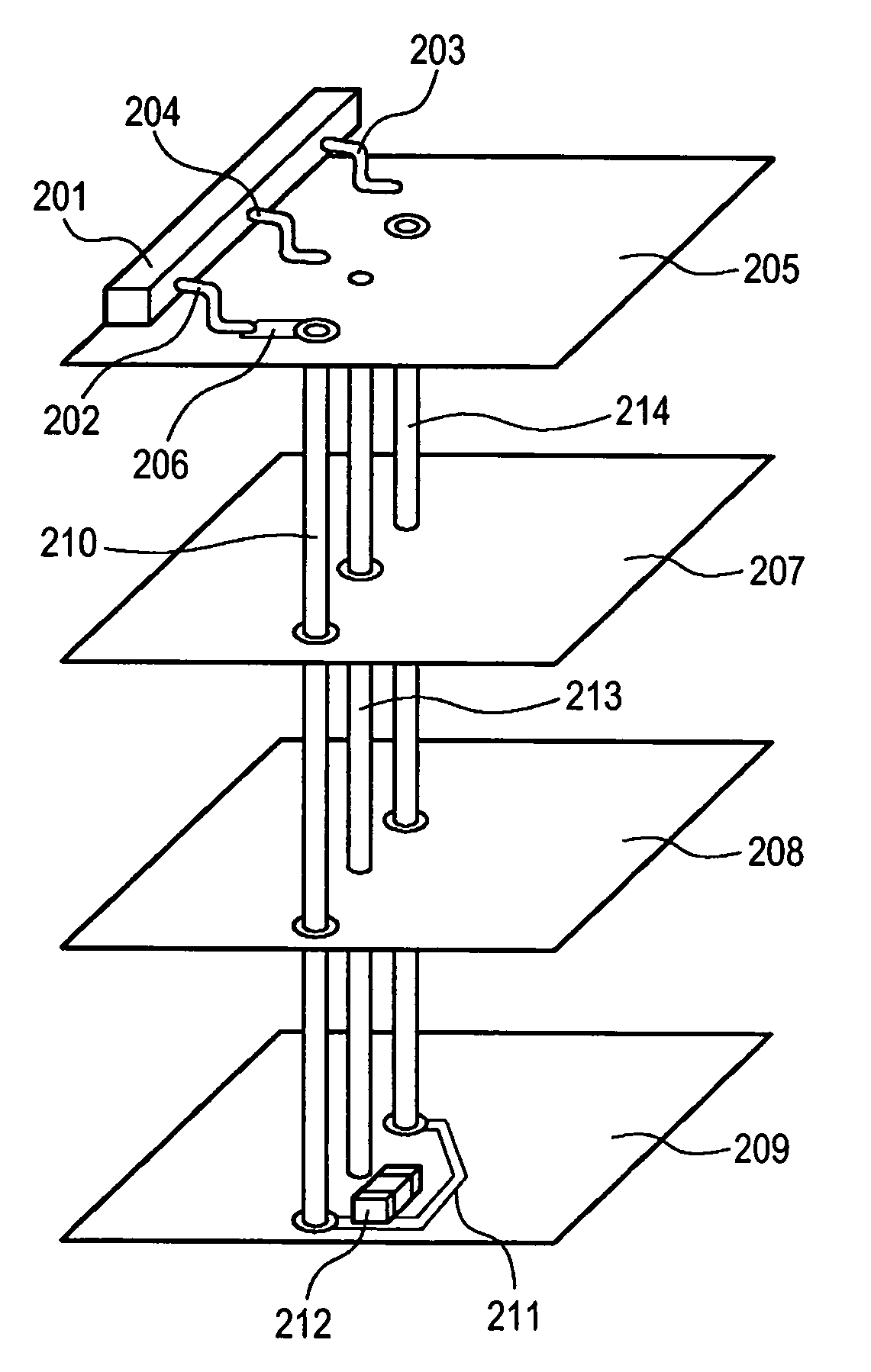
Multilayered printed circuit board
a printed circuit board and multi-layer technology, applied in the field of multi-layer printed circuit boards, can solve the problems of changing power supply and ground potential, affecting the operation of the circuit itself, so as to achieve the effect of effectively using a bypass capacitor and suppressing radiated nois
- Summary
- Abstract
- Description
- Claims
- Application Information
AI Technical Summary
Benefits of technology
Problems solved by technology
Method used
Image
Examples
first embodiment
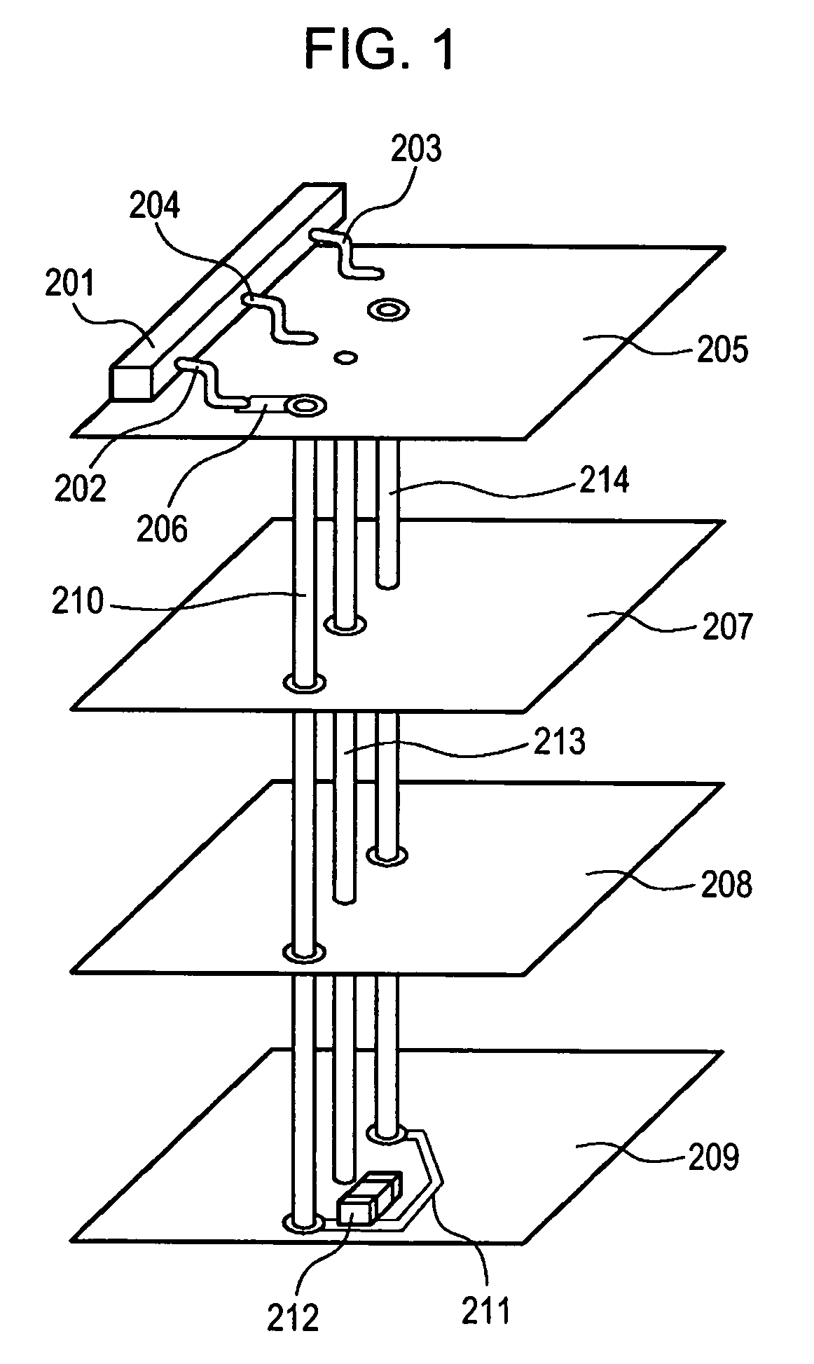
[0038]FIG. 1 is a schematic diagram showing a printed circuit board according to a first embodiment of the present invention.
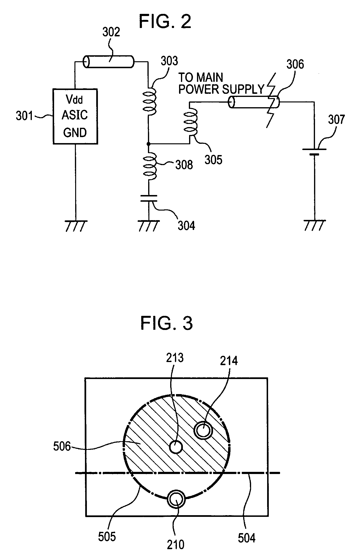
[0039]In FIG. 1, the printed circuit board includes an IC 201 that generates noise, a power supply terminal 202 that supplies power to the IC 201, a ground terminal 203 that supplies a reference potential to the IC 201, and an I / O terminal 204 having a predetermined function for the IC 201. The printed circuit board further includes a first surface-layer conductor 205 on which the IC 201 is mounted, and first power supply wiring 206 installed in the first surface-layer conductor 205. The printed circuit board further includes an inner-layer main power supply plane 207 that constitutes a power supply system of the printed circuit board and that is disposed directly under the first surface-layer conductor 205, an inner-layer ground conductor 208, and a second surface-layer conductor 209 on a face of the printed circuit board opposite to a face of the printed cir...
second embodiment
[0055]FIG. 5 is a schematic diagram showing a second embodiment according to the present invention. In FIG. 5, a printed circuit board includes an IC 601 that generates noise, a power supply terminal 602 that supplies power to the IC 601, a ground terminal 603 that supplies a reference potential to the IC 601, and an I / O terminal 604 having a predetermined function for the IC 601. The printed circuit board further includes a first surface-layer conductor 605 on which the IC 601 is mounted, and first power supply wiring 606 installed in the first surface-layer conductor 605. The printed circuit board further includes an inner-layer main power supply plane 607 that constitutes a power supply system of the printed circuit board and that is disposed directly under the first surface-layer conductor 605, an inner-layer ground conductor 608, and a second surface-layer conductor 609 on a face of the printed circuit board opposite to a face of the printed circuit board on which the first sur...
third embodiment
[0058]FIG. 6 is a sectional view showing the structure of a printed circuit board according to a third embodiment of the present invention. A power supply pin 702 of an IC 701 of the QFP type or small outline package (SOP) type is attached to first power supply wiring 706 provided on the printed circuit board by soldering. Second power supply wiring 711 for attaching a bypass capacitor 712 is provided on a second surface-layer conductor 709 that is provided on a face of the printed circuit board opposite to a face of the printed circuit board on which a first surface-layer conductor 705 is provided.
[0059]The printed circuit board includes four wiring layers having an insulating substrate 720. First to fourth layers are disposed in this order from the top. An inner-layer main power supply plane 707 is provided in the second layer, and an inner-layer ground plane 708 is provided in the third layer. A second power-supply via hole 714 with an inside diameter less than 0.4 mm connects th...
PUM
 Abstract
Description
Claims
Application Information
 - R&D
- Intellectual Property
- Life Sciences
- Materials
- Tech Scout
- Unparalleled Data Quality
- Higher Quality Content
- 60% Fewer Hallucinations
Browse by: Latest US Patents, China's latest patents, Technical Efficacy Thesaurus, Application Domain, Technology Topic, Popular Technical Reports.
© 2025 PatSnap. All rights reserved.Legal|Privacy policy|Modern Slavery Act Transparency Statement|Sitemap|About US| Contact US: help@patsnap.com


