Locking ring for graphite electrodes

a technology of graphite electrodes and locking rings, which is applied in the direction of fastening means, rod connections, mechanical devices, etc., can solve the problems of reducing the effectiveness of the electrode column in conducting electrical current, joint separation, and joint damage, so as to reduce or eliminate the tendency of electrode joints, improve strength and stability, and improve resistance to unscrewing

Inactive Publication Date: 2008-12-16
GRAFTECH INT HLDG INC
View PDF12 Cites 0 Cited by
  • Summary
  • Abstract
  • Description
  • Claims
  • Application Information

AI Technical Summary

Benefits of technology

[0016]It is another aspect of the present invention to provide a locking ring for the end faces of graphite electrodes which reduces or eliminates the tendency of electrode joints to come unscrewed.
[0017]It is yet another aspect of the present invention to provide a locking ring for the end faces of graphite electrodes which produces electrode column joints having improved strength and stability.
[0018]Still another aspect of the present invention is a graphite electrode joint, having improved resistance to unscrewing as compared to art-conventional graphite electrode joints.
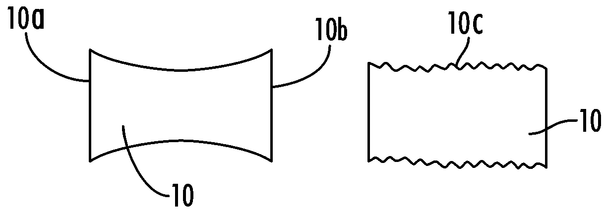
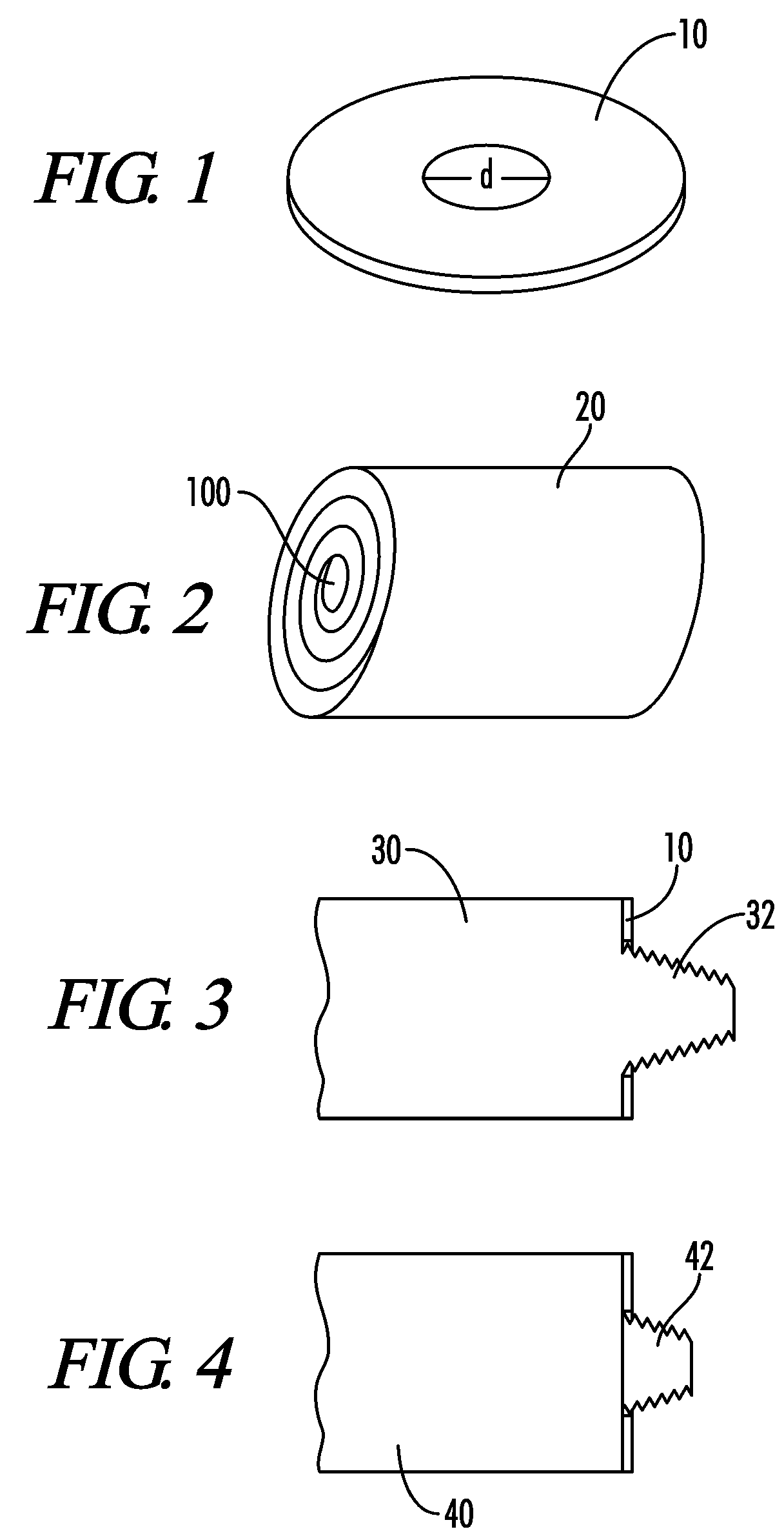
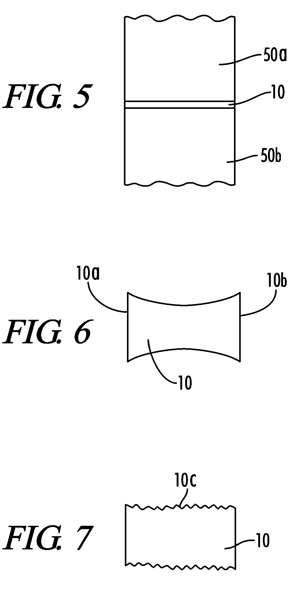
[0022]In addition to being formed of a compressible material such as spiral wound sheets of compressed particles of exfoliated graphite, the inventive locking ring can be shaped so as to increase its compressibility, such as by molding. For example, the sheet can be molded so as to assume a concave shape when viewed along the plane of the end faces of one or both of the electrodes between which the locking ring is situated. The space between the tapered “arms” at either end of the concavity provides even greater potential for compressibility. Moreover, a ramming paste, cement or other putty-like material can be positioned in the concave space. Another way compressibility of the spiral wound exfoliated graphite sheets can be increased is by forming a “rippled” or “corrugated” surface of the locking ring, also by molding. The concave or corrugated surfaces of the locking ring are, of course, one or both of the surfaces which abut the respective electrode end faces.

Problems solved by technology

For instance, longitudinal (i.e., along the length of the electrode / electrode column) thermal expansion of the electrodes, especially at a rate different than that of the pin, can force the joint apart, reducing effectiveness of the electrode column in conducting the electrical current.
A certain amount of transverse (i.e., across the diameter of the electrode / electrode column) thermal expansion of the electrode in excess of that of the pin may be desirable to form a firm connection between pin and electrode; however, if the transverse thermal expansion of the electrode greatly exceeds that of the pin, damage to the electrode or separation of the joint may result.
Again, this can result in reduced effectiveness of the electrode column, or even destruction of the column if the damage is so severe that the electrode column fails at the joint section.
When male-female electrodes having blocked threads are employed, however, a gap exists between the two adjoining electrodes in a joint.
Such a gap formed in a joint can lead or oxidation of the threads of the male tang and other joint surfaces, resulting in loss of material and what is referred to as “necking.” Necking occurs when sufficient material is oxidized away from the joint surfaces to narrow and thus weaken the joint between the two end faces.
Necking reduces effectiveness of the electrode column in conducting the electrical current, reduces the mechanical strength of the joint, and can ultimately lead to failure of the joint and catastrophic loss of the electrode column.
For instance, when necking occurs to a significant degree, the vibrations normally experienced by an electrode column in use in the furnace can lead to cracks and ruptures in the male tang, or the female electrode, and separation of the joint and loss of the electrode column below the affected joint.
Moreover, another effect of the thermal and mechanical stresses to which an electrode column is exposed is literal unscrewing of the electrodes forming the joint (or the electrodes and pins forming the joint), due to vibrations and other stresses.
This unscrewing can reduce electrode column efficiency by reducing electrical contact between adjoining electrodes.
In the most severe case, unscrewing can result in loss of the electrode column below the affected joint.
The nature of the Paus and Revilock spacer and its placement, however, is such that a gap is created in the joint where it may not have otherwise been, thereby contributing to joint looseness and potential for failure.

Method used


Image

  • Locking ring for graphite electrodes
  • Locking ring for graphite electrodes
  • Locking ring for graphite electrodes

Examples


Embodiment Construction

[0033]Graphite electrodes can be fabricated by first combining a particulate fraction comprising calcined coke, pitch and, optionally, mesophase pitch or PAN-based carbon fibers into a stock blend. More specifically, crushed, sized and milled calcined petroleum coke is mixed with a coal-tar pitch binder to form the blend. The particle size of the calcined coke is selected according to the end use of the article, and is within the skill in the art. Generally, in graphite electrodes for use in processing steel, particles up to about 25 millimeters (mm) in average diameter are employed in the blend. The particulate fraction preferable includes a small particle size filler comprising coke powder. Other additives that may be incorporated into the small particle size filler include iron oxides to inhibit puffing (caused by release of sulfur from its bond with carbon inside the coke particles), coke powder and oils or other lubricants to facilitate extrusion of the blend.

[0034]After the bl...


PUM

PropertyMeasurementUnit
diameteraaaaaaaaaa
softening pointaaaaaaaaaa
diameteraaaaaaaaaa

Abstract

An electrode joint is presented, the joint including two joined graphite electrodes having blocked threads and having a locking ring interposed between the electrodes, the locking ring composed of a material having a coefficient of friction such that the tendency of the electrode joint to unscrew is retarded.

Description

RELATED APPLICATION[0001]This application is a continuation in part of and commonly assigned U.S. patent application Ser. No. 10 / 760,947, filed on Jan. 20, 2004 now abandoned in the names of Bowman, Wells, Weber and Pavlisin, entitled “End-Face Seal for Graphite Electrodes,” the disclosure of which is incorporated herein by reference.BACKGROUND OF THE INVENTION[0002]1. Technical Field[0003]The present invention relates to a locking ring for graphite electrodes, and a process for preparing the inventive locking ring. More particularly, the invention concerns a ring, advantageously formed of particles of expanded graphite, used at the end faces of graphite electrodes to resist disassembly of graphite electrode joints.[0004]2. Background Art[0005]Graphite electrodes are used in the steel industry to melt the metals and other ingredients used to form steel in electrothermal furnaces. The heat needed to melt metals is generated by passing current through a plurality of electrodes, usuall...

Claims


Application Information

Patent Timeline
Patent Type & Authority Patents(United States)
IPC IPC(8): H05B7/12H05B7/06H05B7/14
CPCH05B7/14Y10T403/556Y02P10/25
Inventor BOWMAN, BRIANFRASTACI, MICHAELWELLS, TERRENCE PATRICK
Owner GRAFTECH INT HLDG INC
Why Eureka
Try Eureka