Organic transistor with fluropolymer banked crystallization well

a fluropolymer and organic transistor technology, applied in the field of integrated circuit (ic) fabrication, can solve the problems of inability to form orthogonal geometries, inability to uniformly grow grains in channels, and varying grain size, and achieves good solvent orthogonality, simple and effective, and large surface energy contrast

Inactive Publication Date: 2013-03-19
SHARP KK
View PDF13 Cites 0 Cited by
  • Summary
  • Abstract
  • Description
  • Claims
  • Application Information

AI Technical Summary

Benefits of technology

[0016]Described herein is a simple and effective way of creating bank structures for small molecule organic semiconductor systems using fluropolymer ink jet printing. Fluropolymers are ideal for solvent orthogonality, creating a large surface energy contrast in order to control the OSC ink spread without contaminating the OSC formulation. The OSC formulations are typically non-polar solvent based and, thus, the fluorinated solvent based systems provide good solvent orthogonality. For the same reason, fluropolymers are commonly used as a gate insulator for top gate organic TFTs. Also, the ability to form fluropolymer banks via direct inkjet printing, as opposed a deposition and patterning processes, makes it possible to integrate these structures within bottom gate process flows without any additional concerns regarding its affect on the printed source-drain and gate insulator layers.
[0017]In addition to the containment of the OSC ink, it is also important to have some control over the OSC crystallization as the solvent evaporates. The use of fluropolymer banking around the OSC print area, in tandem with source-drain metal electrodes, reduces or eliminates the tendency of print edge nucleated grain growth, and drives source-drain mediated systematic grain growth in the channel region. It should be noted however that the above-described banking concept is not limited to any particular material systems and is widely applicable provided the formulations and geometries are tuned appropriately.

Problems solved by technology

Since the OSC print does not have any bank control, edge pinning and nucleation of the grains from the edges result, leading to varying grain size and non-uniform grain growth in the channel.
Lack of OSC containment leads to the inability to form orthogonal geometries due to surface tension dynamics.
Since more solvent is driven to the edges, higher grain sizes are obtained at the edges with increasing non-uniformity closer to the center.
Such non-uniform and unpredictable grain growth is highly undesirable.
However in case of small molecule systems, which are crystallized to form polycrystalline films, there is added complication of the nucleation and grain growth in the film that has to be controlled.
Since the print edges tend to dry first, there is a spontaneous tendency for grain nucleation at the edges.
This situation poses two main problems.
If the surface tension of the substrate forces the formulation into a large nearly circular geometry (as shown), then it is not possible to print very small OSC features.
If the volume dispensed is spread over a large area, then the large spread leads to inadequate volume for large grain growth through the entire print area—leading to small grains in the middle of the print area where the OTFT channel is defined.
In the case of printed small molecule OTFTs, the morphology and patterning of the organic semiconductor (OSC) layer is a challenging problem.
This removal process puts limitations on the types of material surfaces that can be used.
Especially in the case of a bottom gate organic TFT, any plasma step used to remove the bank layer can have detrimental effect on the underlying organic gate insulator layer.
The plasma step can also oxidize or otherwise damage the metal S / D interfaces.
The challenge to these approaches is to ensure that the bank material develops cleanly over the organic gate insulator and the metal source drain electrodes, while still not causing any damage to these structures in the development process.
However, poor grain growth outside the channel area is used as a means to provide for good device isolation.
This concept works only to a limited extent, with off currents>nA (nanoamps), and is not reasonable for scaling and application in practical products.

Method used


Image

  • Organic transistor with fluropolymer banked crystallization well
  • Organic transistor with fluropolymer banked crystallization well
  • Organic transistor with fluropolymer banked crystallization well

Examples


Embodiment Construction

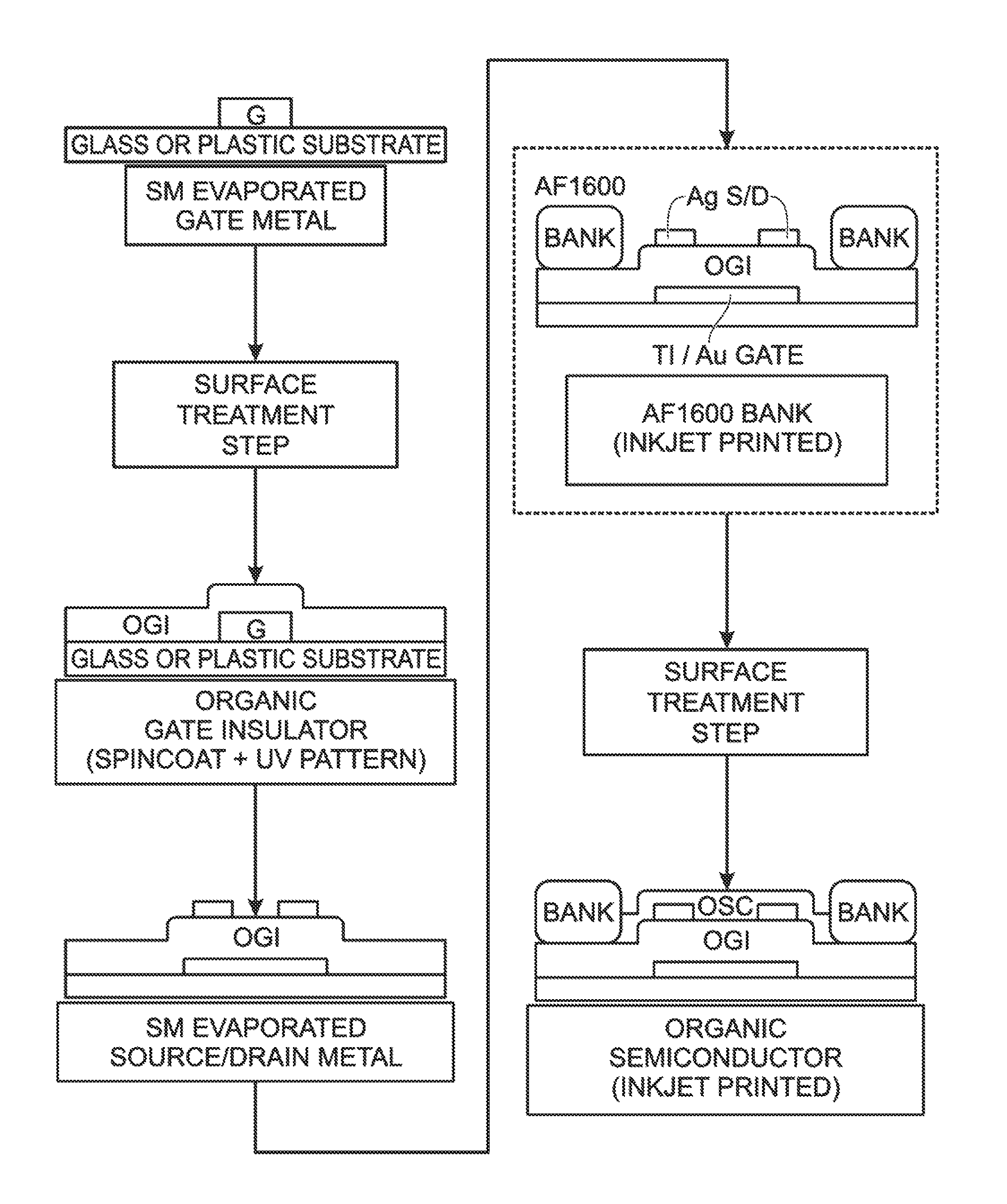
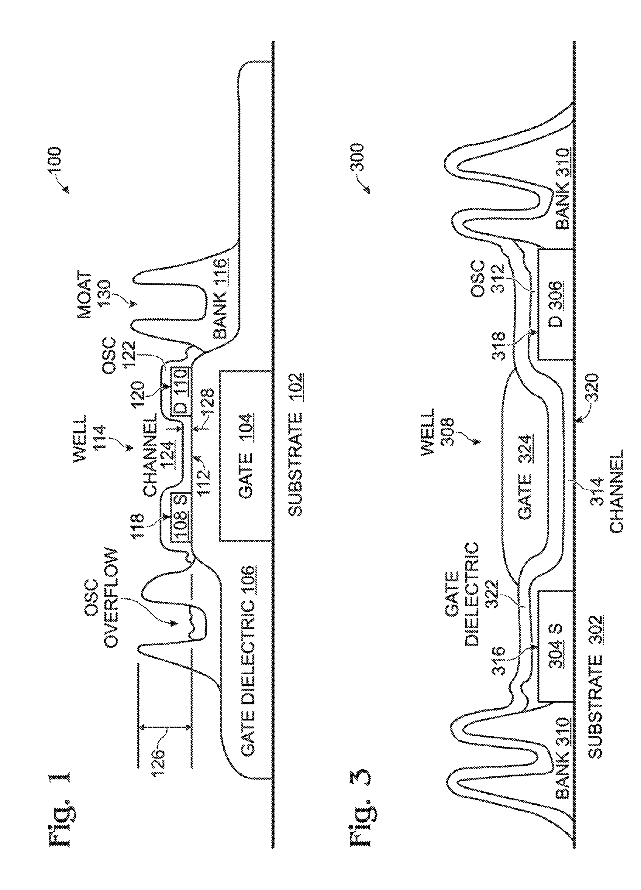
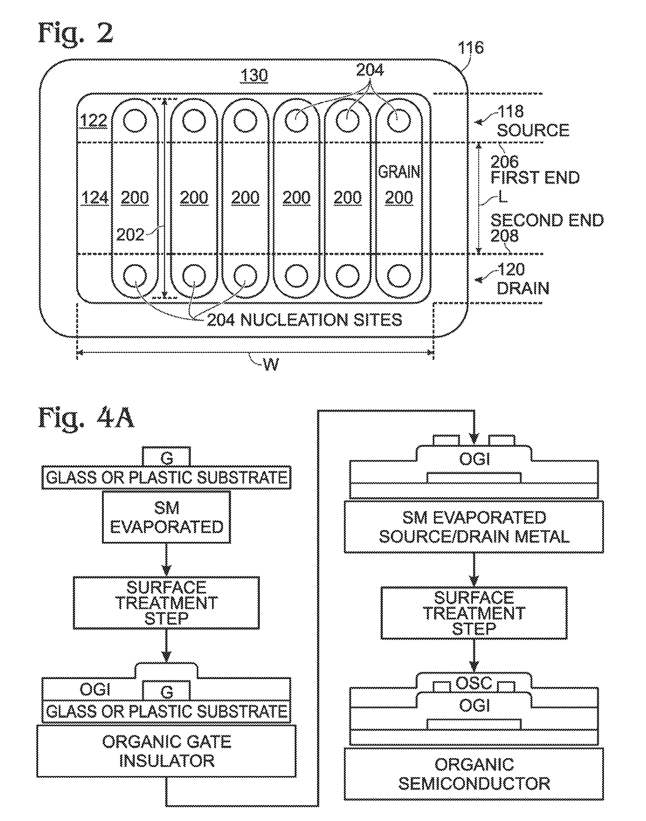
[0028]FIG. 1 is a partial cross-sectional view of a bottom gate organic thin film transistor (OTFT) with a fluropolymer banked crystallization well. The bottom gate OTFT 100 comprises a substrate 102 made from a quartz, glass, plastic, or semiconductor material. A gate electrode 104 overlies the substrate 102, made from a metal or doped semiconductor material. A gate dielectric 106 overlies the gate electrode 104, typically made from an oxide, nitride, or organic gate insulator. A source (S) electrode 108 and a drain (D) electrode 110 overlie the gate dielectric 106, exposing a gate dielectric channel interface region 112 between the S / D electrodes. Typically, the source 108 and drain 110 electrodes are a metal. A well 114 with fluropolymer containment and crystallization banks 116 forms a print area surrounding the gate dielectric channel interface, and at least a portion of the source 108 and drain 110 electrodes. The print area is defined as the gate dielectric channel interface ...


PUM


Abstract

A method is provided for fabricating a printed organic thin film transistor (OTFT) with a patterned organic semiconductor using a fluropolymer banked crystallization well. In the case of a bottom gate OTFT, a substrate is provided and a gate electrode is formed overlying the substrate. A gate dielectric is formed overlying the gate electrode, and source (S) and drain (D) electrodes are formed overlying the gate dielectric. A gate dielectric OTFT channel interface region is formed between the S / D electrodes. A well with fluropolymer containment and crystallization banks is then formed, to define an organic semiconductor print area. The well is filled with an organic semiconductor, covering the S / D electrodes and the gate dielectric OTFT channel interface. Then, the organic semiconductor is crystallized. Predominant crystal grain nucleation originates from regions overlying the S / D electrodes. As a result, an organic semiconductor channel is formed, interposed between the S / D electrodes.

Description

BACKGROUND OF THE INVENTION[0001]1. Field of the Invention[0002]This invention generally relates to integrated circuit (IC) fabrication and, more particularly, to an organic thin-film transistor (OTFT) fabricated using a fluropolymer that is used as a bank for the purposes of containment and crystallization.[0003]2. Description of the Related Art[0004]As noted in Wikipedia, an organic field-effect transistor (OFET) is a transistor that uses an organic semiconductor in its channel. OTFTs are a type of OFET. OTFTs can be prepared either by vacuum evaporation of small molecules, by solution-casting of polymers or small molecules, or by mechanical transfer of a peeled single-crystalline organic layer onto a substrate. These devices have been developed to realize low-cost, large-area electronic products. OTFTs have been fabricated with various device geometries.[0005]Organic polymers, such as poly(methyl-methacrylate) (PMMA), CYTOP, PVA, polystyrene, parylene, etc., can be used as a diel...

Claims


Application Information

Patent Timeline
Patent Type & Authority Patents(United States)
IPC IPC(8): H01L21/40
CPCH01L51/0012H01L51/0516H01L51/0558H01L51/0545H10K71/191H10K10/466H10K10/484H10K10/468
Inventor PUNTAMBEKAR, KANANSTECKER, LISA H.ULMER, KURT
Owner SHARP KK
Why Eureka
Try Eureka