Miniature microphone with balanced termination

a microphone and balanced technology, applied in the field of miniature microphones, can solve the problems of reducing power supply voltage, unable to solve the dynamic range problem, and the intention of providing a microphone assembly with a wide dynamic range, so as to improve the dynamic range, reduce the risk of emi, and reduce the effect of mass production

Active Publication Date: 2008-12-16
TDK CORPARATION
View PDF12 Cites 88 Cited by
  • Summary
  • Abstract
  • Description
  • Claims
  • Application Information

AI Technical Summary

Benefits of technology

[0016]Due to the differential principle a 3 dB increase in dynamic range is obtained, and in addition the differential output signal is less susceptible to EMI. A conventional single-ended transducer element is advantageous with respect to low

Problems solved by technology

Smaller size also means a reduced power supply voltage which contradicts the demand for larger dynamic range.
This may be seen as advantageous in relation to suppress EMI, however, U.S. Pat. No. 6,088,463 does not teach an intention of providing a microphone assembly with a wide dynamic range.
U.S. Pat. No. 6,088,463 is complicated to produce du

Method used


Image

  • Miniature microphone with balanced termination
  • Miniature microphone with balanced termination
  • Miniature microphone with balanced termination

Examples


Embodiment Construction

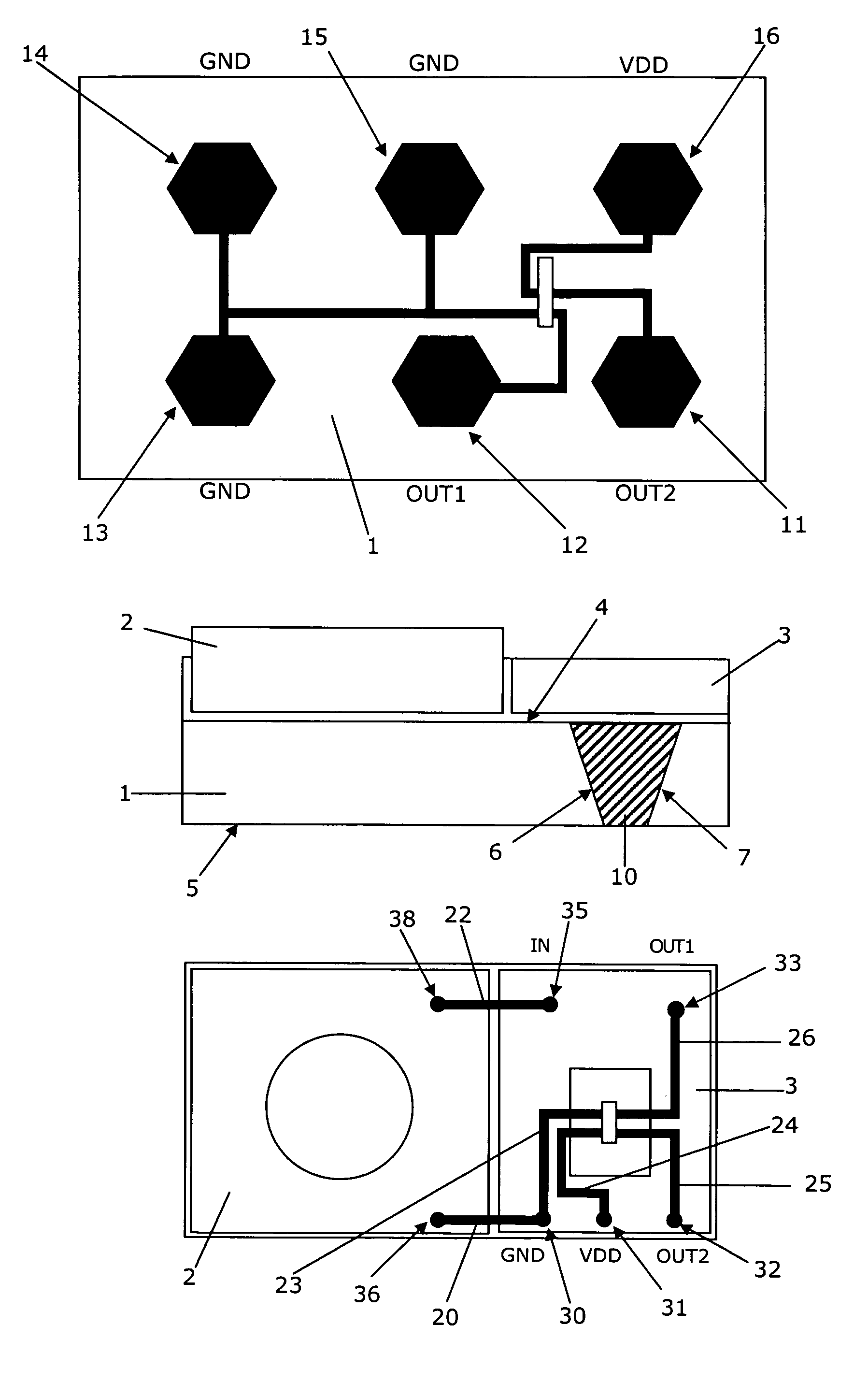
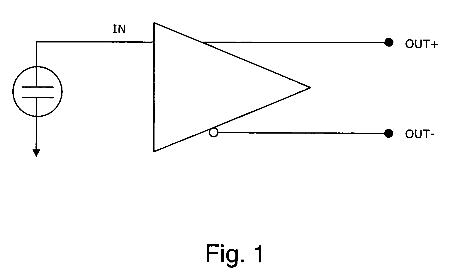
[0021]FIG. 1 shows an electric diagram illustrating the principle of interconnecting and terminating a miniature MEMS microphone according to the present invention. The microphone comprises a single-ended microphone transducer element and an amplifier providing a differential output on terminals OUT+ and OUT−. The single-ended transducer element may be a conventional electret condenser microphone or it may be a silicon-based condenser microphone. This means that the internal connections within the microphone assembly will not benefit from the balancing principle with respect to with reduced susceptibility to electromagnetic interference (EMI). However, the principle can be applied even with a traditional transducer element. Only the preamplifier needs to be adapted for providing a differential output.

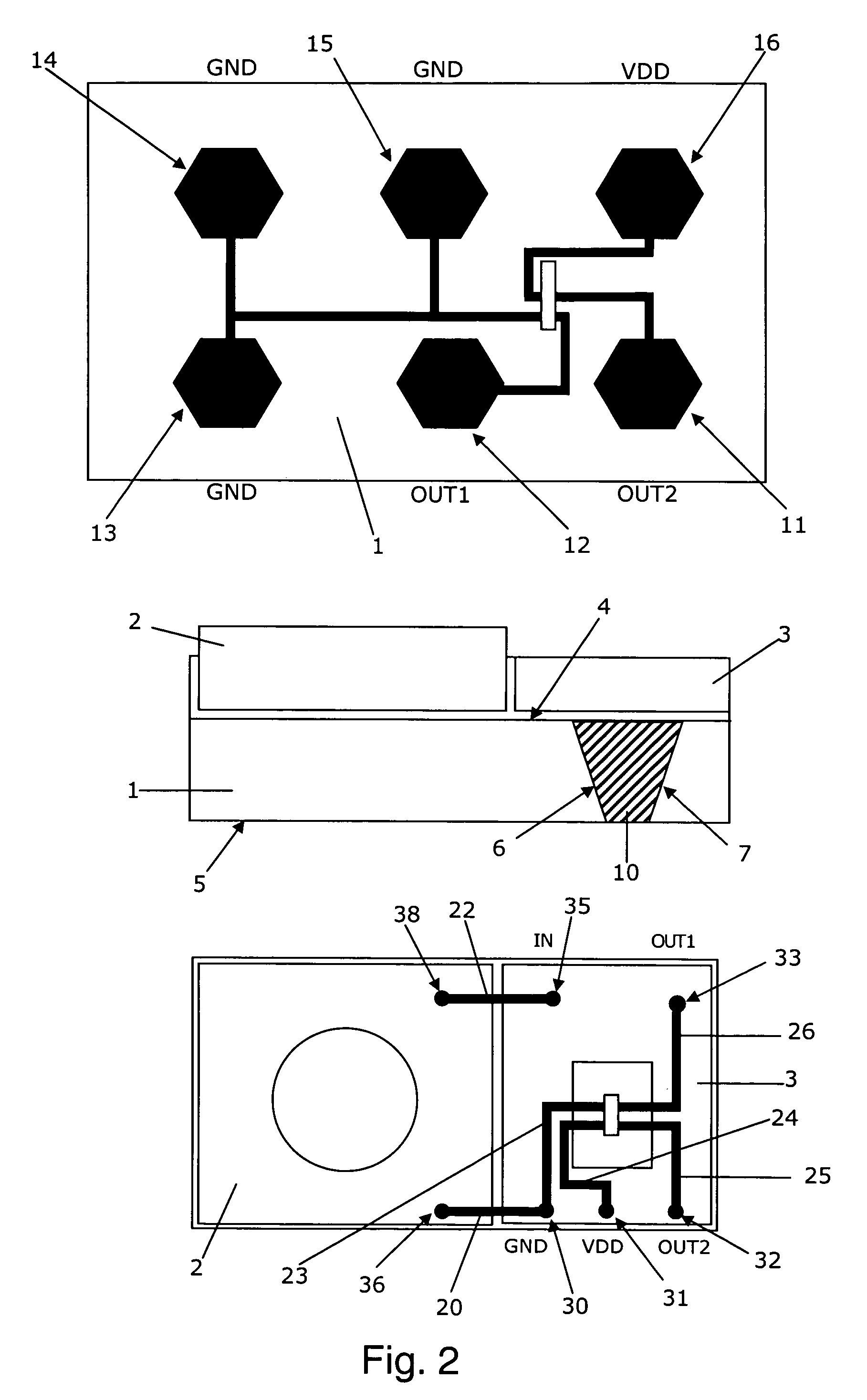
[0022]Since the MEMS microphone can be produce with very small dimensions it is possible to minimise the distance between the transducer element and the amplifier thus the minimising th...


PUM


Abstract

The present invention provides a miniature MEMS microphone comprising a single-ended transducer element connected to an amplifier providing a differential electrical output at terminals arranged at a substantially plane exterior surface. The differential or balanced output signal provides a miniature microphone exhibiting a high dynamic range and a reduced susceptibility to EMI. The microphone is adapted for surface mounting thus the extra output terminal required is still suitable for low cost mass production. In preferred embodiments the transducer element and amplifier are silicon-based. The microphone may have a plurality of separate single-ended transducer elements connected to separate amplifiers providing separate differential outputs. The microphones according to the invention are advantageous for applications within for example hearing aids and mobile equipment.

Description

FIELD OF THE INVENTION[0001]The present invention relates to the field of miniature microphones. In particular, the present invention relates to miniature MEMS microphones with a high dynamic range while still suitable for low cost mass production.BACKGROUND OF THE INVENTION[0002]Practically all miniature consumer applications such as hearing aids, mobile phones and similar require microphone assemblies with still larger dynamic range in combination with still smaller size and a low electromagnetic interference (EMI) sensitivity. Smaller size also means a reduced power supply voltage which contradicts the demand for larger dynamic range.[0003]U.S. Pat. No. 6,088,463 describes a silicon-based miniature microphone assembly. It is mentioned, column 3, fines 36-40, that it is possible to produce an embodiment with a diaphragm arranged between two backplates. This may be seen as advantageous in relation to suppress EMI, however, U.S. Pat. No. 6,088,463 does not teach an intention of prov...

Claims


Application Information

Patent Timeline
IPC IPC(8): H04R25/00H04R19/00H04R19/01H04R19/04
CPCH04R19/04H04R19/005H04R19/016H04R25/00H04R2225/49H04R2430/21
Inventor STENBERG, LARS JORNMULLENBORN, MATTHIASMUCHA, IGOR
Owner TDK CORPARATION
Why Eureka
Try Eureka