
Cycle count storage systems

a storage system and cycle count technology, applied in the field of nonvolatile memory systems, can solve the problems of less than the optimal wear leveling, erroneous data to be read, and the storage level shifts, and achieves the effect of low corruption risk and high degree of reliability

Active Publication Date: 2008-12-16
SANDISK TECH LLC
View PDF39 Cites 52 Cited by
  • Summary
  • Abstract
  • Description
  • Claims
  • Application Information

AI Technical Summary

Benefits of technology

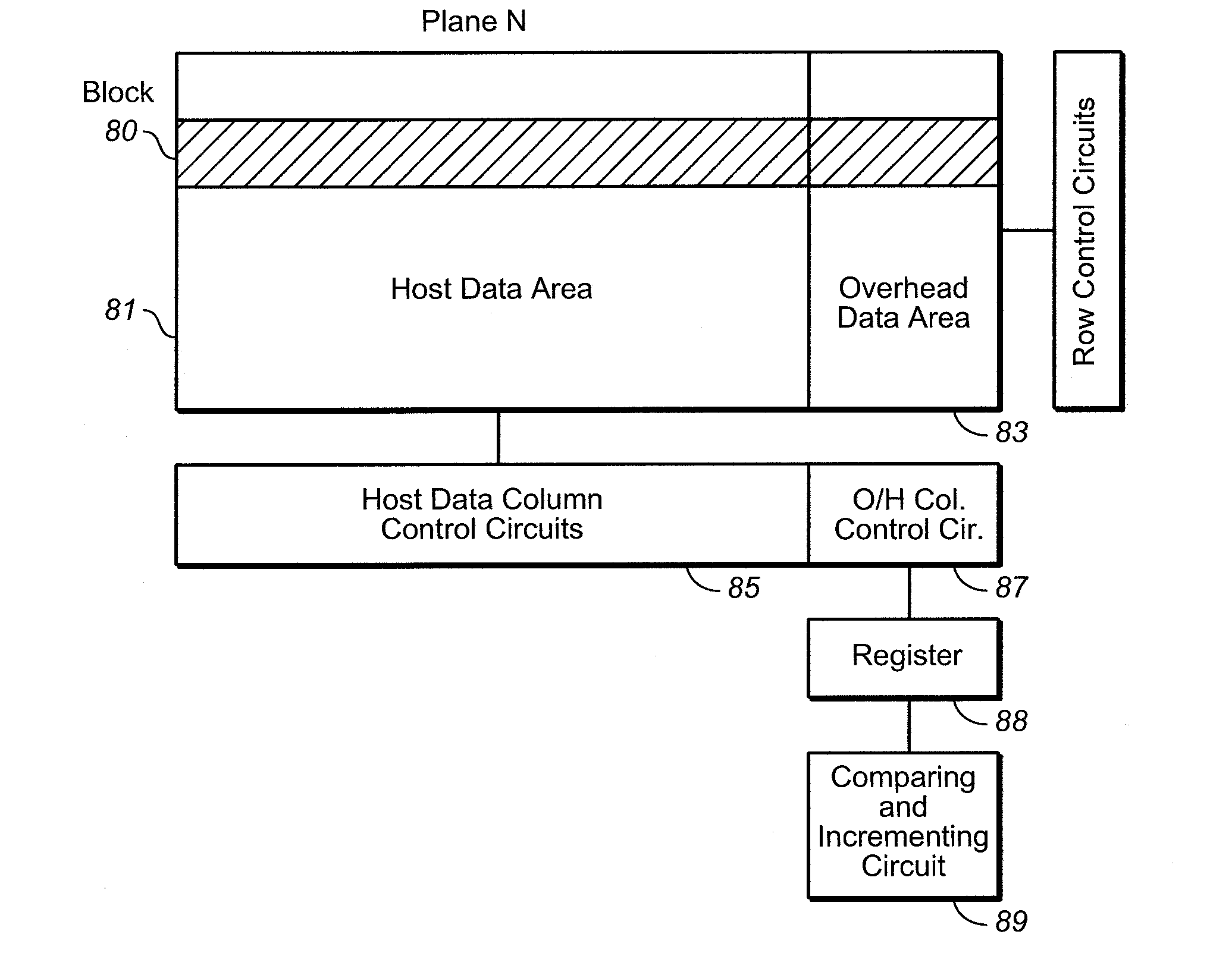
The patent describes a technology that allows for the maintenance of hot counts in a memory array, even when there is no power. This is achieved by using dedicated circuits on the same chip as the memory array, which allows for independent maintenance of hot counts. This improves performance by allowing the controller to perform other functions while the hot counts are maintained. The hot counts are stored in a specific area of the memory array and are copied to a register when an erase command is received. The hot counts are then compared with threshold values to determine what actions to take, such as disabling or modifying the block. This technology also allows for the use of multi-level storage and provides a low risk of corruption of the hot count value. Additionally, dedicated circuits are provided for each plane of the memory to update hot counts quickly and reliably.

Problems solved by technology

These storage levels do shift as a result of charge disturbing programming, reading or erasing operations performed in neighboring or other related memory cells, pages or blocks.
Also, shifting charge levels can be restored back to the centers of their state ranges from time-to-time, before disturbing operations cause them to shift completely out of their defined ranges and thus cause erroneous data to be read.
Zones are primarily used to simplify address management such as logical to physical translation, resulting in smaller translation tables, less RAM memory needed to hold these tables, and faster access times to address the currently active region of memory, but because of their restrictive nature can result in less than optimum wear leveling.
As an erase block goes through successive program and erase cycles, it experiences wear that can eventually cause the block to fail.
However, maintaining hot count values for all the blocks of a memory array uses valuable controller resources.
In particular, where the memory array contains a large number of blocks, the burden of maintaining and updating hot counts may be significant.
Also, the communication associated with monitoring and updating hot counts may use some of the communication capacity between a controller and memory chips, thus slowing other communication and reducing access times.

Method used


Image

  • Cycle count storage systems
  • Cycle count storage systems
  • Cycle count storage systems

Examples


Embodiment Construction

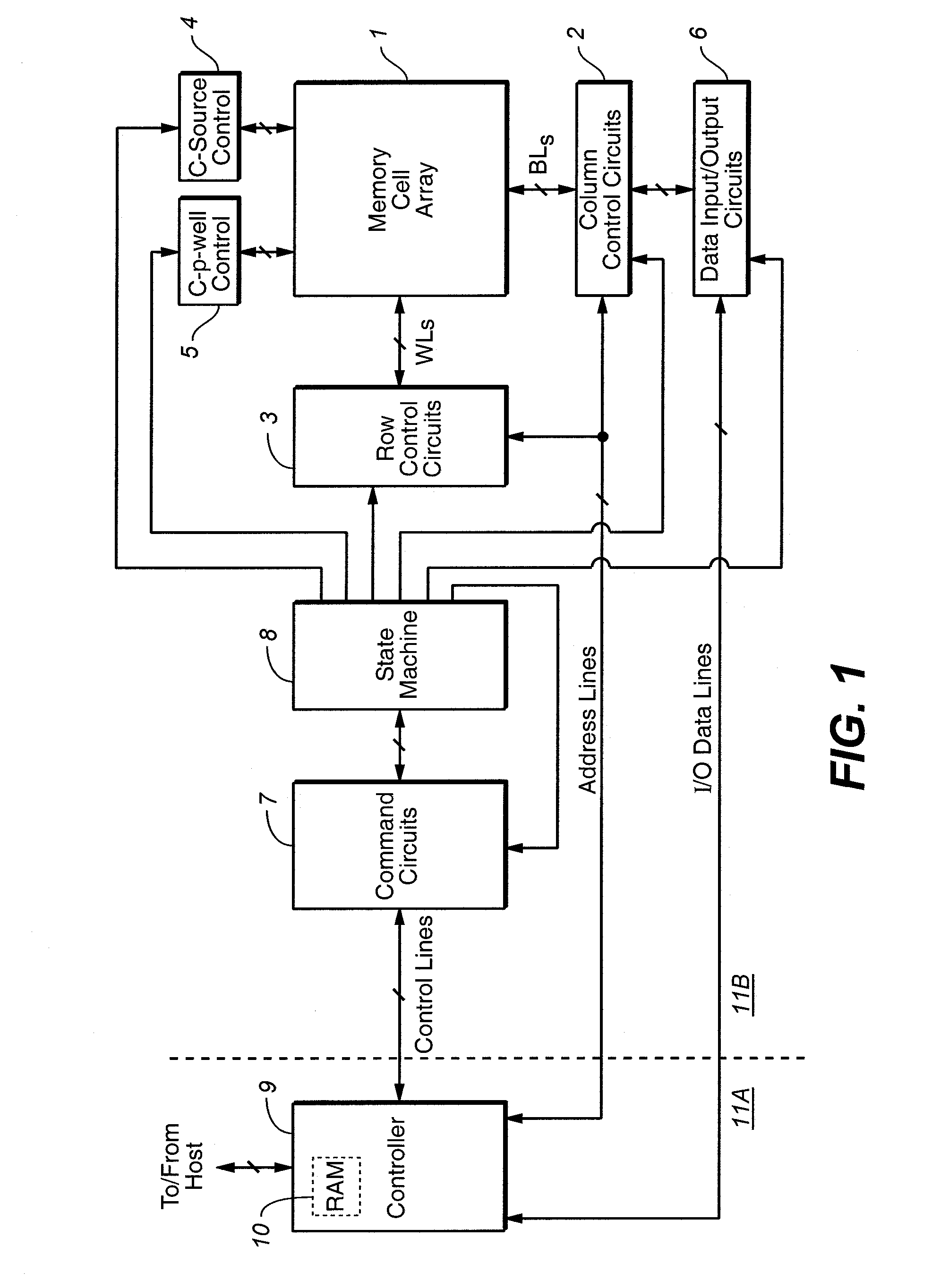
[0033]An exemplary memory system in which the various aspects of the present invention may be implemented is illustrated by the block diagram of FIG. 1. A memory cell array 1 including a plurality of memory cells arranged in a matrix is controlled by column control circuits 2, row control circuits 3, a c-source control circuit 4 and a c-p-well control circuit 5. The memory cell array 1 is, in this example, of the NAND type that is described above in the Background and in references incorporated herein by reference. Other types of nonvolatile memory may also be used. Column control circuits 2 are connected to bit lines (BL) of the memory cell array 1 for reading data stored in the memory cells, for determining a state of the memory cells during a program operation, and for controlling potential levels of the bit lines (BL) to promote the programming or to inhibit the programming. Row control circuits 3 are connected to word lines (WL) to select one of the word lines (WL), to apply re...


PUM


Abstract

A hot count records the number of erase operations experienced by a block. The hot count is stored in an overhead data area of the block and is updated by circuits located on the same substrate as the block. Where a memory has two or more planes, each plane has circuits for updating hot counts.

Description

CROSS-REFERENCE TO RELATED APPLICATION[0001]This application is related to U.S. patent application Ser. No. 11 / 404,672, entitled, “Cycle Count Storage Methods”, filed on the same day as the present application; which application is incorporated in its entirety by reference as if fully set forth herein.BACKGROUND OF THE INVENTION[0002]This invention relates generally to non-volatile memory systems and their operation. All patents, published patent applications and other materials referred to in this application are hereby incorporated by reference in their entirety for all purposes.[0003]There are many commercially successful non-volatile memory products being used today, particularly in the form of small form factor cards, which employ an array of flash EEPROM (Electrically Erasable and Programmable Read Only Memory) cells formed on one or more integrated circuit chips. A memory controller, usually but not necessarily on a separate integrated circuit chip, interfaces with a host to ...

Claims


Application Information

Patent Timeline
Patent Type & Authority Patents(United States)
IPC IPC(8): G06F12/00
CPCG06F12/0246G06F2212/1036G06F2212/7211
Inventor YERO, EMILIO
Owner SANDISK TECH LLC
Learn More