Temperature fuse, and battery using the same
a technology of thermal fuse and thermal fuse, which is applied in the direction of batteries, primary cell maintenance/servicing, cell components, etc., can solve the problems of conventional thermal fuse not being used as a thermal fuse for breaking a high voltage or a large current, sealing to deteriorate or otherwise damage the insulating case, etc., to prevent the seal from deteriorating, suppress the pressure rise of the space in the thermal fuse, and reduce the amount of flux vaporized due to the ar
- Summary
- Abstract
- Description
- Claims
- Application Information
AI Technical Summary
Benefits of technology
Problems solved by technology
Method used
Image
Examples
exemplary embodiment 1
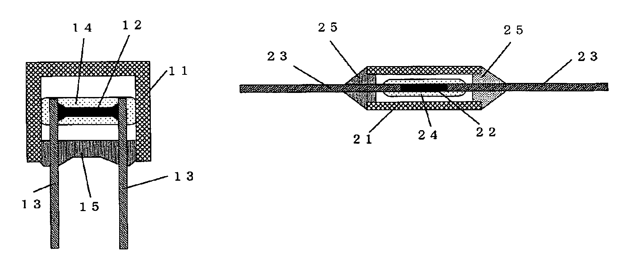
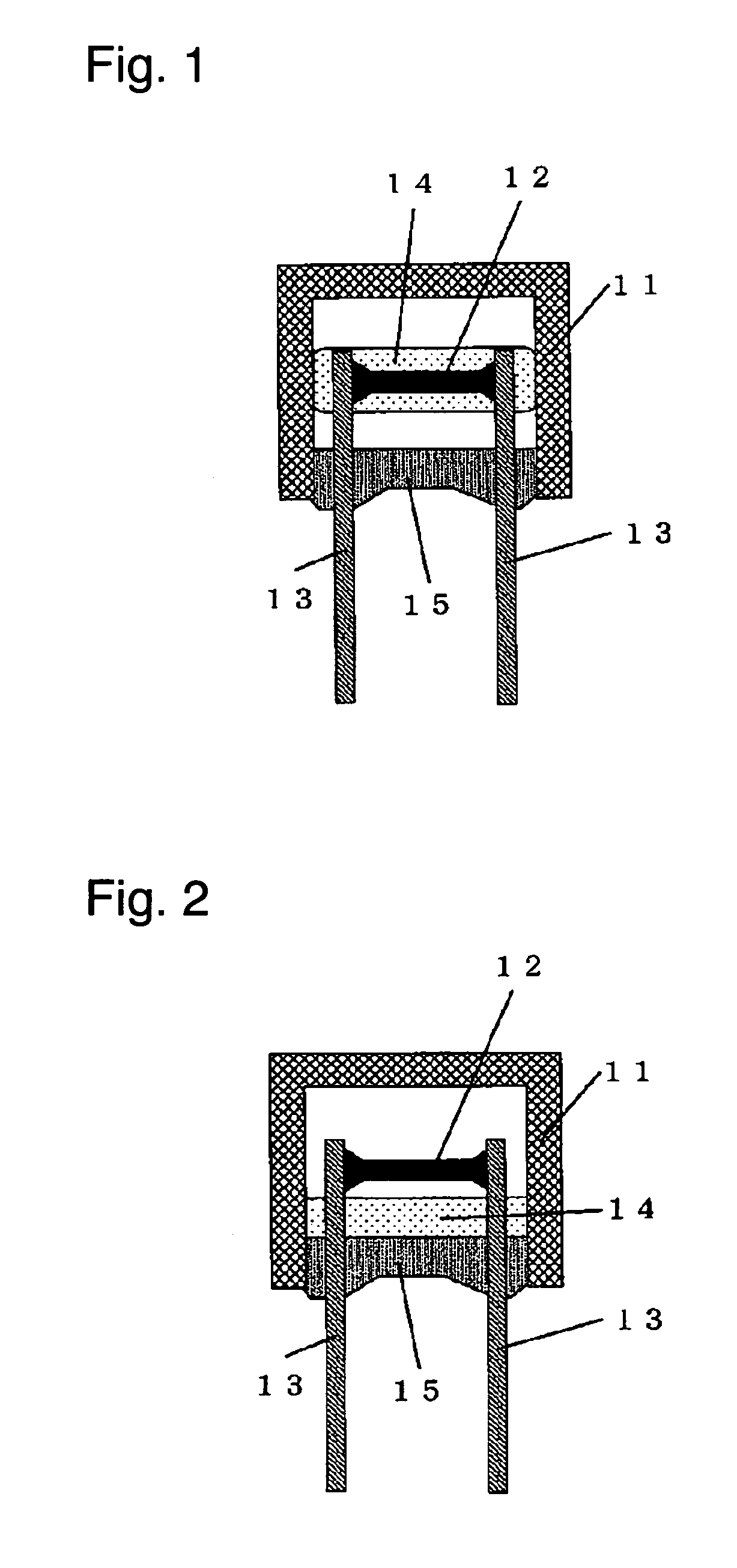
[0038]FIG. 1 is a sectional view of a radial-type thermal fuse according to Exemplary Embodiment 1 of the present invention. FIG. 2 is a sectional view of the thermal fuse having melting flux. A cylindrical or rectangular insulating case 11 having a bottom and having an opening provided therein is made of one of polybutylene telephthalate (PBT), polyphenylene sulfide (PPS), polyethylene telephthalate (PET), phenol resin, ceramic, and glass. Fusible alloy 12 having substantially a cylindrical or rectangular shape is provided in the insulating case 11. The fusible alloy 12 is made of one of tin, lead, zinc, bismuth, indium, cadmium, silver, copper, and alloy of these metals. Respective ends of a pair of lead conductors 13 are connected to respective ends of the fusible alloy 12. Respective other ends of the lead conductors 13 are led out of the insulating case 11 through the opening of the insulating case 11. The lead conductors 13 have a wire shape and may be made of single metal, su...
exemplary embodiment 2
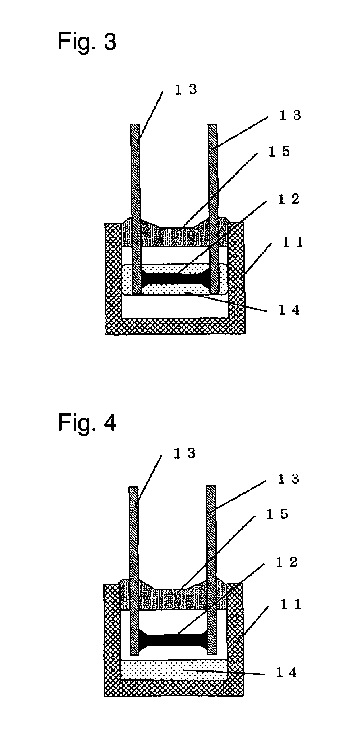
[0041]FIG. 3 is a sectional view of a radial-type thermal fuse according to exemplary Embodiment 2 of the present invention. FIG. 4 is a sectional view of the thermal fuse having melting flux. The thermal fuse of Embodiment 2 includes the same components as those of a thermal fuse of Embodiment 1 shown in FIGS. 1 and 2. The fuse of embodiment 2 is configured differently from that of Embodiment 1, specifically, the volume of a space in an insulating case 11 between a fusible alloy 12 and a bottom of an insulating case 11 is larger than the volume of flux 14, as shown in FIG. 3
[0042]Upon being used on an electronic device or a heating component, such as a transformer or a motor, as shown in FIG. 4, the radial-type thermal fuse of Embodiment 2 is attached to the electronic device or the heating component, so that the space between the fusible alloy 12 and the bottom of the insulating case 11 is positioned substantially in the same direction as the gravity from the fusible alloy 12. Acc...
exemplary embodiment 3
[0043]FIG. 5 is a sectional view of an axial-type thermal fuse according to Exemplary Embodiment 3 of the present invention. FIG. 6 is a sectional view of the thermal fuse having melting flux. An insulating case 21 having a cylindrical or rectangular shape and having openings provided therein is made of one of polybutylene telephthalate (PBT), polyphenylene sulfide (PPS), polyethylene telephthalate (PET), phenol resin, ceramic, and glass. Fusible alloy 22 having substantially a cylindrical or rectangular shape is provided in the insulating case 21. The fusible alloy 22 is made of one of tin, lead, zinc, bismuth, indium, cadmium, silver, copper, and alloy of these metals. Respective ends of a pair of lead conductors 23 are connected to respective ends of the fusible alloy 22. Respective other ends of the lead conductors 23 are led out of the insulating case 21 through the openings of the insulating case 21. The lead conductors 23 have a wire shape and are made of single metal, such a...
PUM
| Property | Measurement | Unit |
|---|---|---|
| volume | aaaaa | aaaaa |
| volume of flux | aaaaa | aaaaa |
| longitudinal length L1 | aaaaa | aaaaa |
Abstract
Description
Claims
Application Information
 - R&D
- Intellectual Property
- Life Sciences
- Materials
- Tech Scout
- Unparalleled Data Quality
- Higher Quality Content
- 60% Fewer Hallucinations
Browse by: Latest US Patents, China's latest patents, Technical Efficacy Thesaurus, Application Domain, Technology Topic, Popular Technical Reports.
© 2025 PatSnap. All rights reserved.Legal|Privacy policy|Modern Slavery Act Transparency Statement|Sitemap|About US| Contact US: help@patsnap.com


