Surface acoustic wave device, method of manufacturing the same, and electronic apparatus

a surface acoustic wave and acoustic wave technology, applied in piezoelectric/electrostrictive/magnetostrictive devices, piezoelectric/electrostriction/magnetostriction machines, electrical apparatus, etc., can solve the problem of suppressing spurious frequency, achieve higher frequency, suppress spurious frequency, and improve ci value and q value

Inactive Publication Date: 2009-01-06
SEIKO EPSON CORP
View PDF21 Cites 12 Cited by
  • Summary
  • Abstract
  • Description
  • Claims
  • Application Information

AI Technical Summary

Benefits of technology

[0019]An advantage of the invention is to improve CI value and Q value by suppressing the spurious effectively in the surface acoustic wave device using the pseudo-longitudinal wave type leaky surface acoustic wave, and thereby to provide a surface acoustic wave device, which facilitates attaining higher frequencies, a method of manufacturing the surface acoustic wave device, and an electronic apparatus including the surface acoustic wave device.
[0020]According to a first aspect of the invention, a surface acoustic wave device includes a lithium-tantalate substrate and an IDT electrode that excites a pseudo-longitudinal wave type leaky surface acoustic wave in the surface of the lithium-tantalate substrate, wherein a normalized substrate thickness t / λ, which is the thickness t of the lithium-tantalate substrate normalized by an IDT wavelength λ, is in a range of 1≦t / λ≦22.
[0021]According to this configuration, the surface acoustic wave device whose spurious frequency is suppressed can be provided using the pseudo-longitudinal wave type leaky surface acoustic wave that propagates in the lithium-tantalate substrate. Moreover, in the case of an oscillator forming an oscillator circuit, problems, such as an abnormal oscillation and a frequency jump, can be prevented, and thus an oscillator with high stability can be provided.
[0022]According to a second aspect of the invention, it is preferable that in the surface acoustic wave device according to the first aspect, the cut-out angle of the surface of the lithium-tantalate substrate and the propagation direction of the pseudo-longitudinal wave type leaky surface acoustic wave are in a range of (90°, 90°, 0° through 180°) in Euler representation.
[0023]According to this configuration, it is possible to generate the pseudo-longitudinal wave type surface acoustic wave whose phase velocity is twice as fast as the Rayleigh wave, and the higher frequencies of the surface-acoustic wave device will be facilitated.
[0024]According to a third aspect of the invention, a surface acoustic wave device includes a lithium-niobate substrate and an IDT electrode that excites a pseudo-longitudinal wave type leaky surface acoustic wave in the surface of the lithium-niobate substrate, wherein a normalized substrate thickness t / λ, which is the thickness t of the lithium-niobate substrate normalized by an IDT wavelength λ, is in a range of 1≦t / λ≦29.

Problems solved by technology

Because the phase velocity of the pseudo-longitudinal wave type leaky surface acoustic wave is fast, there is a possibility to easily realize higher frequencies of the surface acoustic wave device, which has been difficult to realize with the Rayleigh wave, the leaky surface acoustic wave or the like.
However, it has been confirmed that when using the pseudo-longitudinal wave type leaky surface acoustic wave using the lithium-tantalate substrate, the lithium-niobate substrate, or the tetraboric-acid lithium substrate having an advantage of a large electromechanical coupling coefficient, a spurious frequency occurs in the range of the conventionally disclosed cut-out angle of the piezo-electric substrate, which is practically disadvantage.
For example, if the spurious occurs near the principal vibration in using the surface acoustic wave device as a resonator, CI (crystal impedance) value and Q value will be reduced, and also in the case of an oscillator forming an oscillator circuit, the spurious will be the causes of producing problems such as an abnormal oscillation, a frequency jump, and the like.
Furthermore, when used as a filter, there is a problem that the spurious frequency has to be suppressed as much as possible over a wide range of the pass band from the need for securing a flat delay characteristic.

Method used


Image

  • Surface acoustic wave device, method of manufacturing the same, and electronic apparatus
  • Surface acoustic wave device, method of manufacturing the same, and electronic apparatus
  • Surface acoustic wave device, method of manufacturing the same, and electronic apparatus

Examples


first embodiment

A First Embodiment

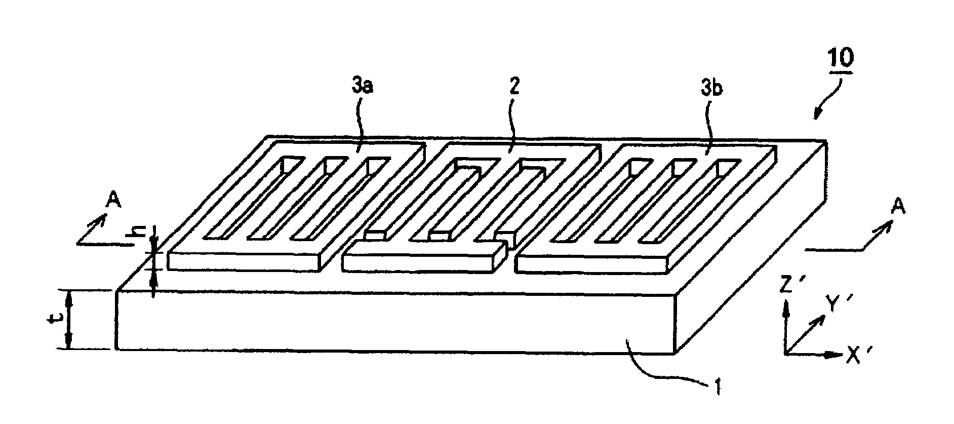
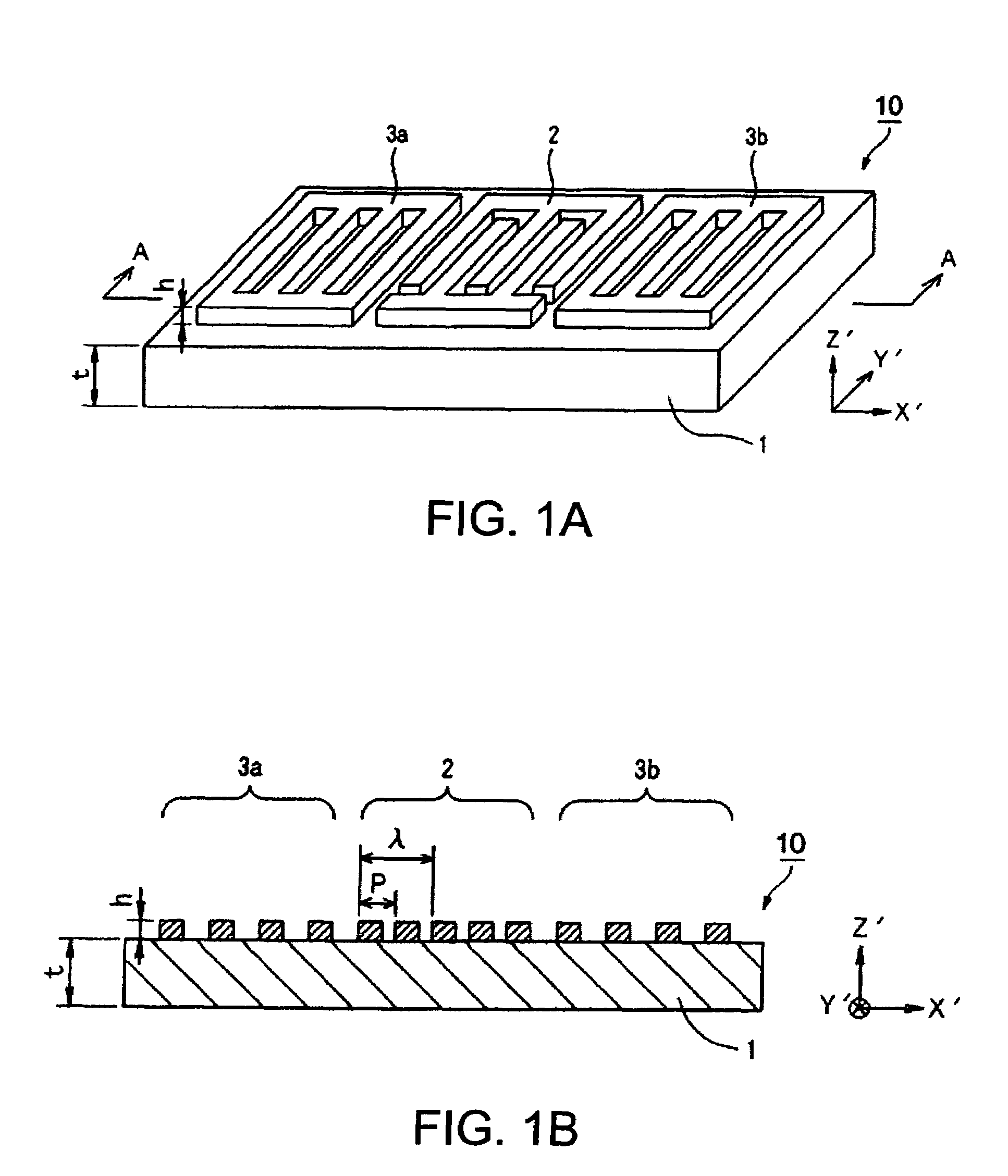
[0062]FIG. 1A is a perspective view showing a schematic configuration of a surface acoustic wave element concerning an embodiment, and FIG. 1B is the A-A sectional view of FIG. 1A.

[0063]A surface acoustic wave element 10 includes: a piezo-electric substrate 1 including the lithium-tantalate substrate, the lithium-niobate substrate, or the tetraboric-acid lithium substrate; and an IDT electrode 2 as well as reflector electrodes 3a and 3b formed on the surface of this piezo-electric substrate 1.

[0064]In FIG. 1, t is the thickness of the piezo-electric substrate 1, P is the pitch of the IDT electrode 2, λ is the IDT wavelength, and h is the thickness of the IDT electrode 2 and reflector electrodes 3a and 3b.

[0065]When the lithium-tantalate substrate is used as the piezo-electric substrate 1, the cut-out angle of the surface of the piezo-electric substrate 1 and the propagation direction (hereinafter, referred to as a “cut-out angle”) of the pseudo-longitudinal wave t...

second embodiment

A Second Embodiment

[0089]Next, an embodiment of an electronic apparatus concerning the invention will be described.

[0090]FIG. 7 is a schematic configuration view showing the configuration of the electronic apparatus. For example, a surface acoustic wave device 30 is provided in an electronic apparatus 60, such as a cellular phone and a keyless entry system. In the case of the cellular phone, the surface acoustic wave device 30 is used as a frequency selective filter, and in the case of the keyless entry system, the surface acoustic wave device 30 is used as a resonator of an oscillator. That is, the electronic apparatus 60 concerning this embodiment contains the surface acoustic wave device 30 as a filter or a resonator.

[0091]According to the electronic apparatus 60 comprising of such a configuration, it is possible to provide the electronic apparatus 60 using a filter and a resonator whose spurious is suppressed by using the pseudo-longitudinal wave type leaky surface acoustic wave...

third embodiment

A Third Embodiment

[0092]Next, an embodiment of a method of manufacturing the surface acoustic wave device concerning the invention will be described. FIG. 8 is a flow chart explaining the embodiment of the method of manufacturing the surface acoustic wave device. Here, the process until the surface acoustic wave element 10 shown in FIG. 1 is housed in the housing case 14 shown in FIG. 5, and completed as the surface acoustic wave device 30 will be described.

[0093]First, the thickness t of the piezo-electric substrate 1 is adjusted (Step S1). This piezo-electric substrate 1 is formed from the lithium-tantalate substrate, the lithium-niobate substrate, or the tetraboric-acid lithium substrate, and the cut-out angle of the substrate surface is cut out in a range of the angle described above, respectively. Adjustment of the thickness t of this piezo-electric substrate 1 is carried out shaving the front and back of the substrate uniformly by polish or etching. At this time, the thickness...


PUM


Abstract

A surface acoustic wave device, comprising a lithium-tantalate substrate and an IDT electrode that excites a pseudo-longitudinal wave type leaky surface acoustic wave in the surface of the lithium-tantalate substrate, wherein a normalized substrate thickness t / λ, which is a thickness t of the lithium-tantalate substrate normalized by an IDT wavelength λ, is in a range of 1≦t / λ≦22.

Description

BACKGROUND OF THE INVENTION[0001]1. Technical Field[0002]The present invention relates to a surface acoustic wave device using a pseudo-longitudinal wave type leaky surface acoustic wave, a method of manufacturing the surface acoustic wave device, and an electronic apparatus using the surface acoustic wave device.[0003]2. Related Art[0004]A surface acoustic wave device is comprised of a surface acoustic wave element having an IDT electrode provided in the surface of a piezo-electric substrate, and is used in telecommunications apparatus and the like as circuit elements, such as a resonator and a filter.[0005]As the surface acoustic wave used for the surface acoustic wave device, Rayleigh wave and a leaky surface acoustic wave (Leaky wave) are mainly used.[0006]The Rayleigh wave is a surface wave propagating in the surface of an elastic body, and the energy thereof propagates without radiating into the piezo-electric substrate. Although there exist three types of volume waves (bulk w...

Claims


Application Information

Patent Timeline
Patent Type & Authority Patents(United States)
IPC IPC(8): H01L41/00H03H3/08H03H3/10H03H9/02H03H9/145H03H9/25
CPCH03H3/10H03H9/02559H03H9/02614H03H9/02818H03H9/02984H03H9/1071H03H9/14538
Inventor OSHIO, MASAHIRO
Owner SEIKO EPSON CORP
Why Eureka
Try Eureka