
Spark plug for internal combustion engine and method of manufacturing the same

a technology for internal combustion engines and spark plugs, which is applied in the manufacture of spark plugs, spark plugs, machines/engines, etc., can solve the problems of inability to manufacture spark plugs, troublesome gas tightness, and inability to form local recesses, so as to eliminate a factor affecting productivity and ensure stable and efficient manufacturing.

Active Publication Date: 2009-01-13
NGK SPARK PLUG CO LTD
View PDF15 Cites 18 Cited by
  • Summary
  • Abstract
  • Description
  • Claims
  • Application Information

AI Technical Summary

Benefits of technology

The invention is about a spark plug with a gasket that prevents gas leakage and ensures the gas-tightness of the spark plug. The gasket has a solid annular shape and a groove portion formed over its entire periphery. The gasket is securely fitted in the metal shell of the spark plug and is compressed during installation, reducing crushing deformation and preventing variation in deformation. The gasket is designed to come off the pawl portions formed on the metal shell, preventing the gasket from coming off and causing a problem in the gas-tightness of the spark plug. The technical effect of the invention is to provide a reliable and stable gas seal for the spark plug and prevent issues related to gas leakage.

Problems solved by technology

However, in the case of the solid gasket with such as an annular disk shape, since the pawl portions are formed, there is a possibility of local recesses being formed at peripheral portions of the pawl portions.
For this reason, it is apprehended that the gas leaks through the recesses, disadvantageously causing trouble in the gas-tightness.
In addition, as the plurality of pawl portions are projectingly formed, the pawl portions are caught at the thread, and a measure can be thereby provided for preventing the spark plug from coming off in the axial direction of the plug, but once the spark plug is fitted, the following problem can possibly occur.
In this case, in a case where an attempt is made to remove the spark plug by loosening the thread, or after its removal, there is a possibility that an inner end of the pawl portion which became thin-walled may undesirably enter the trough of the externally threaded portion, and the gasket may relatively rotate along the trough and may undesirably come off finally from the spark plug.
In addition, there is also a possibility of coming off during the mounting operation owing to the variation of the cut bending.

Method used


Image

  • Spark plug for internal combustion engine and method of manufacturing the same
  • Spark plug for internal combustion engine and method of manufacturing the same
  • Spark plug for internal combustion engine and method of manufacturing the same

Examples


Embodiment Construction

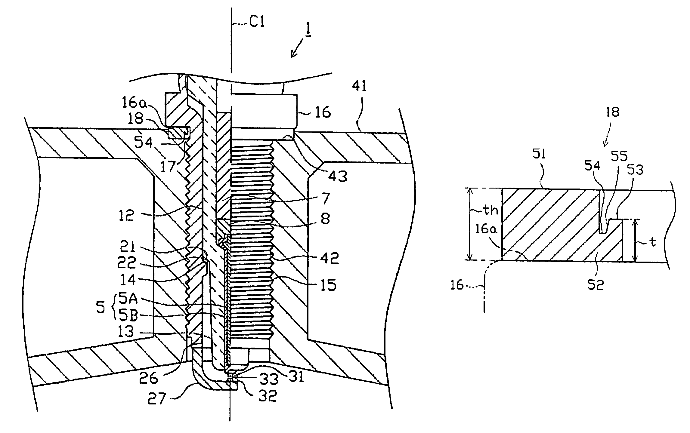
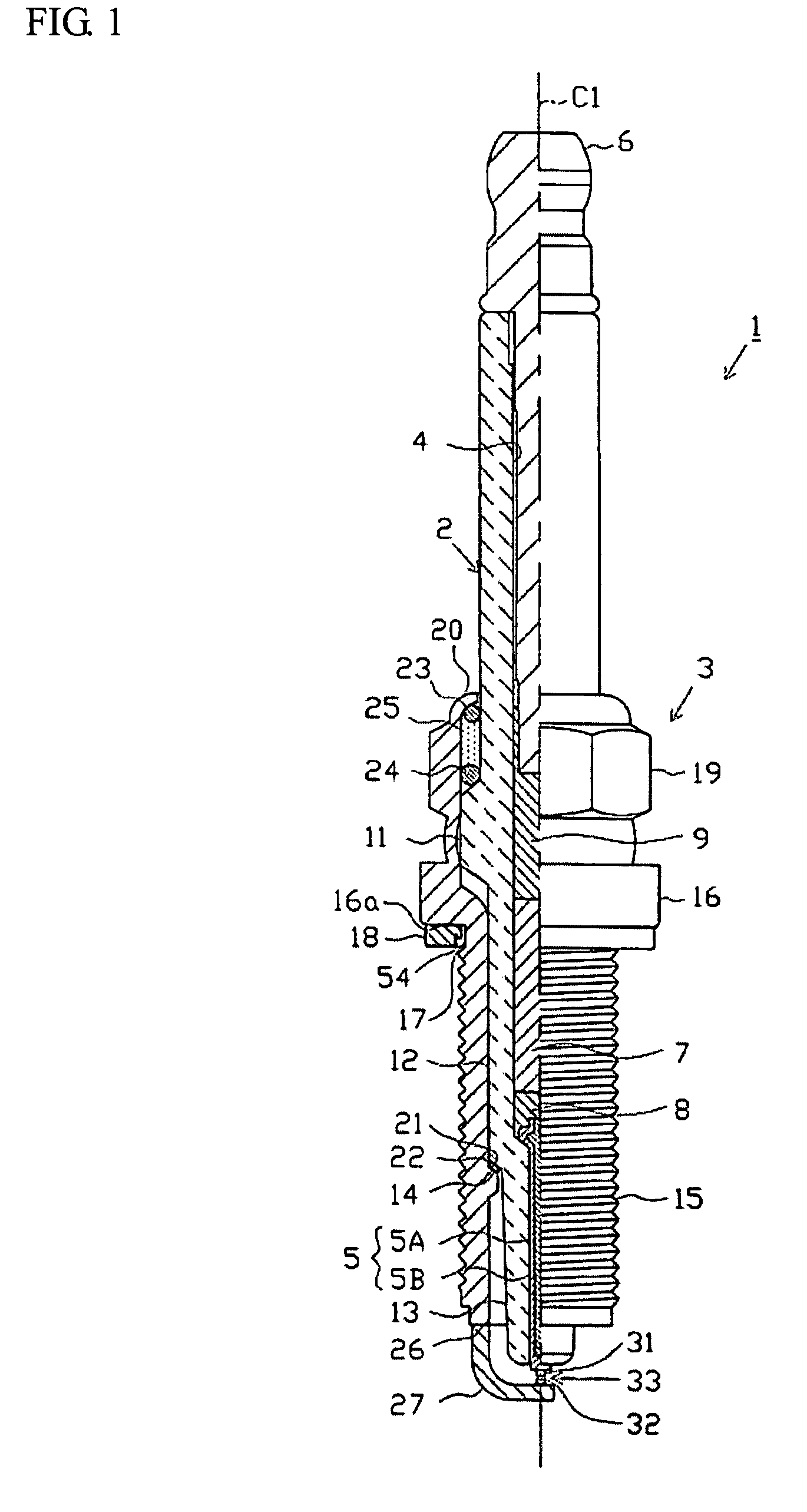
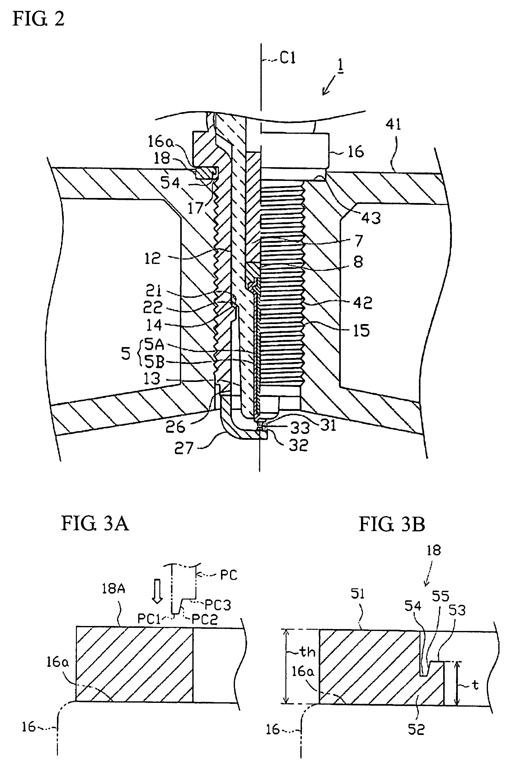
[0053]Hereafter, a description will be given of an embodiment of the invention with reference to the drawings. FIG. 1 is a fragmentary front elevational view illustrating a spark plug 1. It should be noted that a description will be given by assuming that, in FIG. 1, the direction of an axis C1 of the spark plug 1 is a vertical direction in the drawing, and that the lower side of the drawing is a leading end side of the spark plug 1 and the upper side is a rear end side thereof.

[0054]The spark plug 1 is comprised of a cylindrical insulator 2, a cylindrical metal shell 3 for holding it, and the like.

[0055]An axial hole 4 is penetratingly formed in the insulator 2 along the axis C1. A center electrode 5 is inserted and fixed in a leading end portion side of the axial hole 4, and a terminal electrode 6 is inserted and fixed in a rear end portion side thereof. A resistor 7 is disposed between the center electrode 5 and the terminal electrode 6 inside the axial hole 4, and opposite end p...


PUM


Abstract

A spark plug for an internal combustion engine includes: a cylindrical insulator as defined herein; a center electrode as defined herein; a cylindrical metal shell as defined herein; and a ground electrode as defined herein, an annular gasket receiving portion projecting radially outward being provided on a rear end side of the externally threaded portion of the metal shell, and a metallic gasket capable of abutting against the gasket receiving portion being provided on the outer periphery of the metal shell, wherein the gasket has a solid annular shape, an inside diameter of the gasket is smaller than an outside diameter of the externally threaded portion, and a groove portion whose depth coincides with the direction of the axis is provided over an entire circumference of the gasket.

Description

FIELD OF THE INVENTION[0001]The present invention relates to a spark plug for use in an internal combustion engine, and more particularly to a spark plug having a gasket provided on an outer periphery of a metal shell and a method of manufacturing the same.BACKGROUND OF THE INVENTION[0002]A general spark plug which is used for igniting an internal combustion engine such as an automotive gasoline engine is comprised of a center electrode, an insulator provided on its outer periphery, a cylindrical metal shell provided on the outer periphery of the insulator, and a ground electrode having a proximal end portion joined to a leading end portion of the metal shell. An externally threaded portion is formed on the outer peripheral surface of the metal shell, and an annular gasket receiving portion projecting in a radially outward direction is formed on a rear end side of the externally threaded portion. Meanwhile, a threaded hole having an internally threaded portion is formed in a cylinde...

Claims


Application Information

Patent Timeline
Patent Type & Authority Patents(United States)
IPC IPC(8): H01T13/08
CPCH01T13/08
Inventor FUKUZAWA, REIMONKYUNO, JIRO
Owner NGK SPARK PLUG CO LTD
Learn More