Rotor and electrical generator

a technology of electrical generators and rotors, applied in the direction of wind energy generation, motors, dynamo-electric machines, etc., can solve the problems of complex multi-stage gearboxes, unnecessary gearboxes, and require maintenance, so as to improve the size to weight and/or power to weight performan

Inactive Publication Date: 2009-01-27
GOLIATH WIND
View PDF40 Cites 65 Cited by
  • Summary
  • Abstract
  • Description
  • Claims
  • Application Information

AI Technical Summary

Benefits of technology

[0023]It is a particular object of the present invention to provide a rotor, and especially a rotor for a low speed generator driven directly or via a low-ratio gearing by a wind or marine current turbine, which can be economically fabricated on

Problems solved by technology

However, multi-stage gearboxes are complex, heavy, costly, require maintenance and there have been reliability issues in wind turbine applications.
These generators are designed to provide the required electrical output whilst rotating at the same speed as the turbine, thereby making the gearbox unnecessary.
Existing direct-drive turbines will become impractical if simply scaled up from existing designs because of problems associated with manufacture, weight and transportation of components of such extreme dimensions.
However, for example, a 5 MW direct drive generator would need to be approximately 15 meters in diameter and would be extremely heavy.
There are several problem areas arising from the size and weight of these generators.
This is even more problematic for the export market(v) installation at the tower head(vi) tower head weight impact on other aspects of the wind turbine design
Whilst this structure gives high peripheral

Method used


Image

  • Rotor and electrical generator
  • Rotor and electrical generator
  • Rotor and electrical generator

Examples


Embodiment Construction

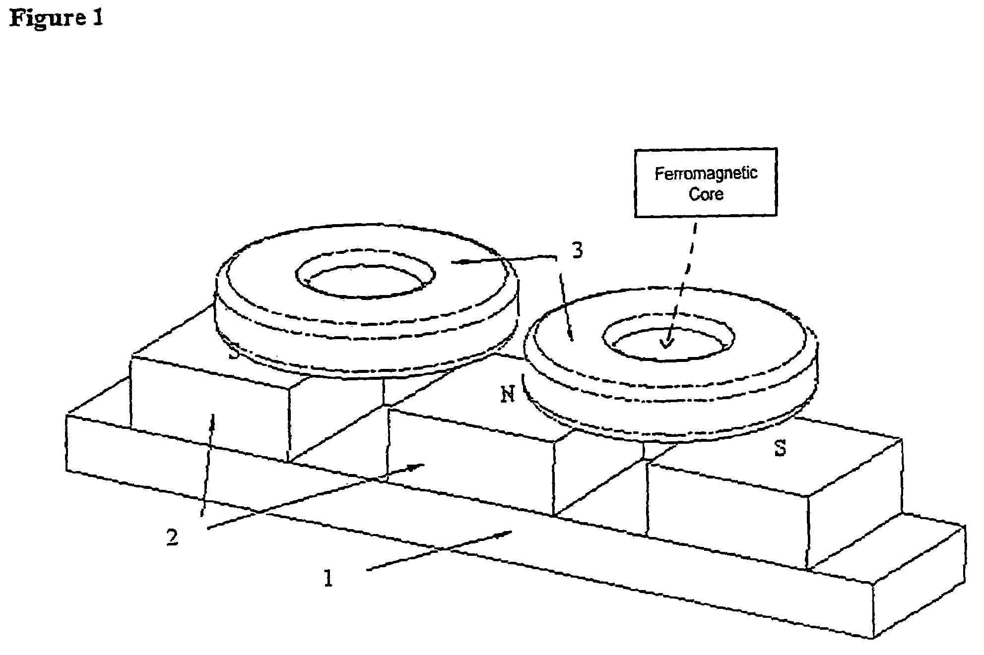
[0060]A preferred electromagnetic configuration is as shown in FIG. 1. In this example a ferromagnetic cylinder (1) makes up the rotor back iron and carries neodymium-iron-boron permanent magnets (2) on its outer surface. These may be fixed in any suitable manner, for example using adhesive, but the magnetic forces alone might be sufficient to retain the magnets in position. The magnets are polarised radially and create a multipolar distribution of magnetic flux in the space surrounding the rotor. The stator structure supports a set of copper coils (3), whose axes are directed radially, on a non magnetic backing (not shown). Adhesive or other fixing may be used to fix them in place. Coils may be embedded in the support structure. This will provide good electrical insulation.

[0061]As the rotor turns the flux linkage with each coil changes cyclically and alternating emf is induced in each coil. In contrast to prior art systems, no iron core is provided for the reasons set out above.

[0...


PUM


Abstract

A rotor for an electrical generator and a generator incorporating such a rotor, the rotor consisting of a central hub, a radially spaced concentric rim portion with rotor magnetic elements mounted upon it, and a plurality of elongate tension members extending generally between the hub and the rim, maintained substantially in tension so as to maintain the rim substantially in compression. The hub is rotatably driven by an axially spaced power drive means such as a wind or marine current turbine.

Description

[0001]This is a nationalization of PCT / GB02 / 02288 filed Jun. 5, 2002 and published in English.BACKGROUND OF THE INVENTION[0002]1. Field of the Invention[0003]The invention relates to a rotor for an electrical generator and to an electrical generator incorporating such a rotor.[0004]In particular the invention relates to a rotor for a low speed generator and to a low speed generator incorporating such a rotor, that is to say a generator in which a driving force is applied to a power means, and in particular a rotating power means such as a turbine, which is mechanically coupled to cause rotation of a rotor either by direct drive or via a low-ratio gearing.[0005]The invention relates especially to the provision of large scale wind turbine generators and marine current turbine generators, and the prior art is discussed and examples of the invention are given in the context of the former in particular. However, it will be understood that the invention finds potential application general...

Claims


Application Information

Patent Timeline
IPC IPC(8): F03D5/04H02K1/18H02K7/18H02K1/30H02K5/04H02K7/08H02K21/14
CPCH02K1/185H02K1/30H02K5/04H02K7/085H02K7/1823Y02E10/725H02K7/1838Y02E10/72
Inventor GORDON, PAULSPOONER, EDWARD
Owner GOLIATH WIND
Why Eureka
Try Eureka