Differential bang-bang phase detector (BBPD) with latency reduction

a technology of phase detector and bang-bang, which is applied in the direction of oscillation comparator circuit, automatic control, instruments, etc., can solve the problems of limiting the operating frequency and data-rate of the communication circuit of the cdr circuitry used in the application, and achieve the effect of improving the performance of the bang-bang phase detection circui

Inactive Publication Date: 2009-01-27
ALTERA CORP
View PDF4 Cites 12 Cited by
  • Summary
  • Abstract
  • Description
  • Claims
  • Application Information

AI Technical Summary

Benefits of technology

[0005]Bang-bang phase detection (BBPD) methods and circuits for high data-rate applications are presented. The methods and circuits may be used to improve the per...

Problems solved by technology

In many digital communications applications and circuits, the performance of the CDR circuitry used in the application limits the operating frequency and data-rate of the commun...

Method used


Image

  • Differential bang-bang phase detector (BBPD) with latency reduction
  • Differential bang-bang phase detector (BBPD) with latency reduction
  • Differential bang-bang phase detector (BBPD) with latency reduction

Examples


Embodiment Construction

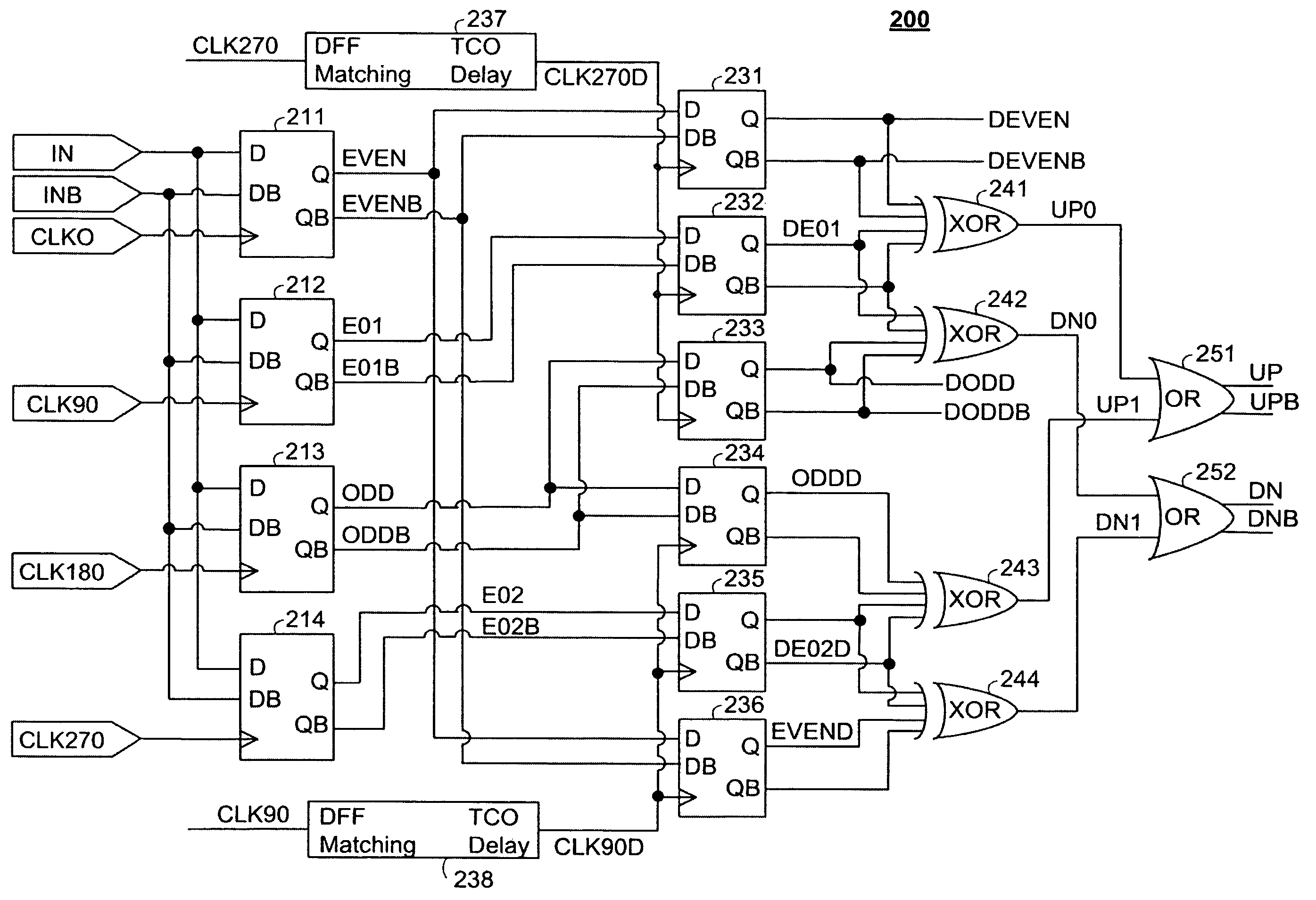
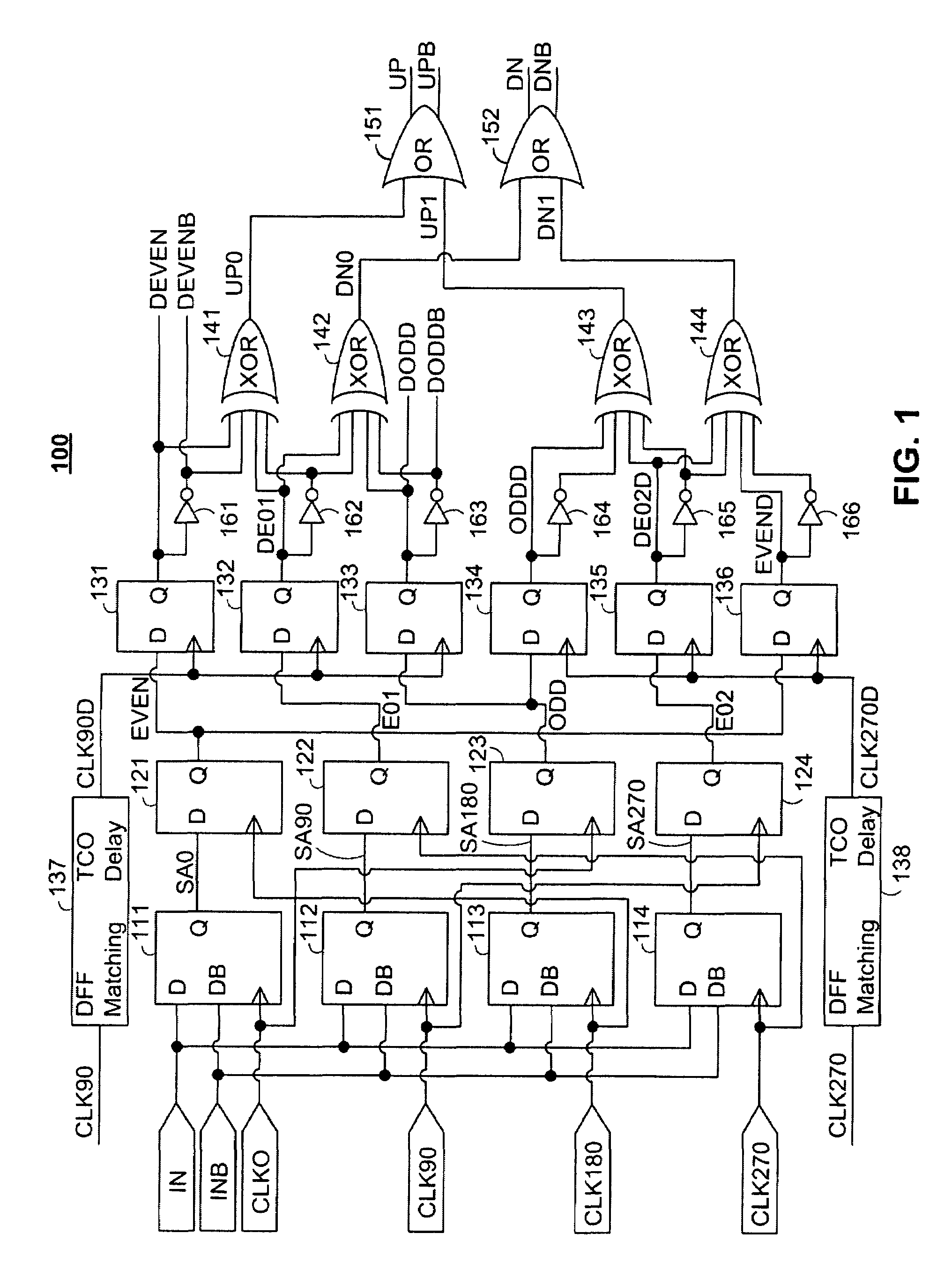
[0014]FIG. 1 shows a schematic diagram of a bang-bang phase detector (BBPD) circuit 100 including first, second and third stages of timing circuitry and first and second stages of combinational logic circuitry. BBPD circuit 100 produces from differential input signals IN / INB received at differential input nodes two sets, UP / UPB and DN / DNB, of differential output signals used to detect the phase of the input signals. BBPD circuit 100 receives four clock signals CLK0, CLK90, CLK180, and CLK270 for timing, and produces two additional delayed clock signals CLK90D and CLK270D.

[0015]BBPD circuit 100 also functions as a differential input sampler that produces two sets, DEVEN / DEVENB and DODD / DODDB, of retimed differential output signals. The first retimed differential output signal, DEVEN / DEVENB, includes the even samples of the input signal (samples 2, 4, . . . ), and the second differential output signal, DODD / DOODB, includes the odd samples of the input signal (samples 1, 3, . . . ). Bo...


PUM


Abstract

Bang-bang phase detection (BBPD) methods and circuits are presented for providing low latency, low jitter phase detection for use in high data-rate applications. A shortened data-path implementation of BBPD methods and circuits provides low-latency production of two output signals including alternating samples of the input signal. Combinational logic circuitry is also provided to produce a clock-data recovery (CDR) signal indicative of the phase of the input signal with respect to a clock signal. The use of differential signals throughout the BBPD timing circuitry provides for the production of a low jitter CDR signal.

Description

BACKGROUND OF THE INVENTION[0001]This invention relates to differential bang-bang phase detection (BBPD) methods and circuits having reduced latency. Methods and circuits are provided to improve the performance of BBPD circuits at high data rates.[0002]The transmission of data at high data rates increasingly depends on the performance of the clock data recovery (CDR) that is used to recover the transmitted data signal from the received signal. High performance CDR circuitry is essential to accurately extract timing information from high-frequency signals and to recover the transmitted data signal from the received signal. In many digital communications applications and circuits, the performance of the CDR circuitry used in the application limits the operating frequency and data-rate of the communication circuit. Improved CDR circuitry is therefore needed in order to increase the data-rate and operating frequency of the communications applications.[0003]The use of bang-bang phase det...

Claims


Application Information

Patent Timeline
IPC IPC(8): H03D13/00
CPCH03D13/004
Inventor NGUYEN, TOAN THANHTRAN, THUNGOC M.
Owner ALTERA CORP
Why Eureka
Try Eureka