Digital electronic support measures

a technology of electronic support measures and digital circuits, applied in the field of digital electronics, can solve the problems of inability to meet the requirements of wide frequency coverage, the limitation of wide-band receiver systems in handling more than one signal at a time, and the high cost of analogue channelised architectures, so as to achieve the effect of simplifying the receiver in the present invention and simple manipulation

Active Publication Date: 2009-01-27
THE SEC OF STATE FOR DEFENCE IN HER BRITANNIC MAJESTYS GOVERNMENT OF THE UK OF GREAT BRITAIN & NORTHERN IRELAND
View PDF18 Cites 12 Cited by
  • Summary
  • Abstract
  • Description
  • Claims
  • Application Information

AI Technical Summary

Benefits of technology

[0012]Such apparatus achieves resolution of the inherent frequency ambiguities at signal levels appropriate for detection requirements, which in general are lower than those needed for phase measurement, as in the current art. A further advantage of employing this invention is that discontinuities at multiples of the sampling rates can be well covered, and overall there are fewer areas of ambiguity. These can thus be set to optimise the system with far greater freedom, and the apparatus requires a minimum of only two channels to operate the system.
[0026]A further advantage of this apparatus is that because it implements an identical set of filters in each channel, signal phase is preserved identically in each channel, even for signals that are aliased into a different frequency bin in each channel. This is so despite the difference in sample frequency. This feature allows phase comparison to be undertaken for the same signal in channels operating with different sample rates. Thus the receiver in the present invention may be further simplified, as one of the three digital receiver channels can be removed, and frequency difference and phase difference information required to span the full frequency range can be captured in only two channels.

Problems solved by technology

The limitations of wide-band receiver systems in handling more than one signal at a time are well known, as is the high cost of analogue channelised architectures.
The existing digital circuitry cannot cope with the wide frequency coverage requirements of Electronic Support Measures and this has militated against the digital approach, necessitating extensive signal conditioning to map the overall input frequency range into multiple narrower bandwidth channels for digital processing.
To handle the full frequency range, it is currently necessary to use multiple digital receivers, which adds significantly to the cost and complexity of any system.
However, in most channelised architectures for radar ESM, the receiver occupancy at any time is fairly sparse, indicating that the resources available are not well utilised.
One of the chief challenges in achieving the goal of developing a digital Electronic Support Measure for radar is to process the wide frequency band required with a much narrower bandwidth receiver, of the order of 1-2 GHz.
However, this aliasing process introduces ambiguities in the frequency measuring process which can severely complicate subsequent analysis of the signal unless they are resolved.
This goes some way towards solving the problem, but still leaves discontinuities at multiples of the sampling frequency, where the frequency of the input signal cannot be determined.

Method used


Image

  • Digital electronic support measures
  • Digital electronic support measures
  • Digital electronic support measures

Examples


Embodiment Construction

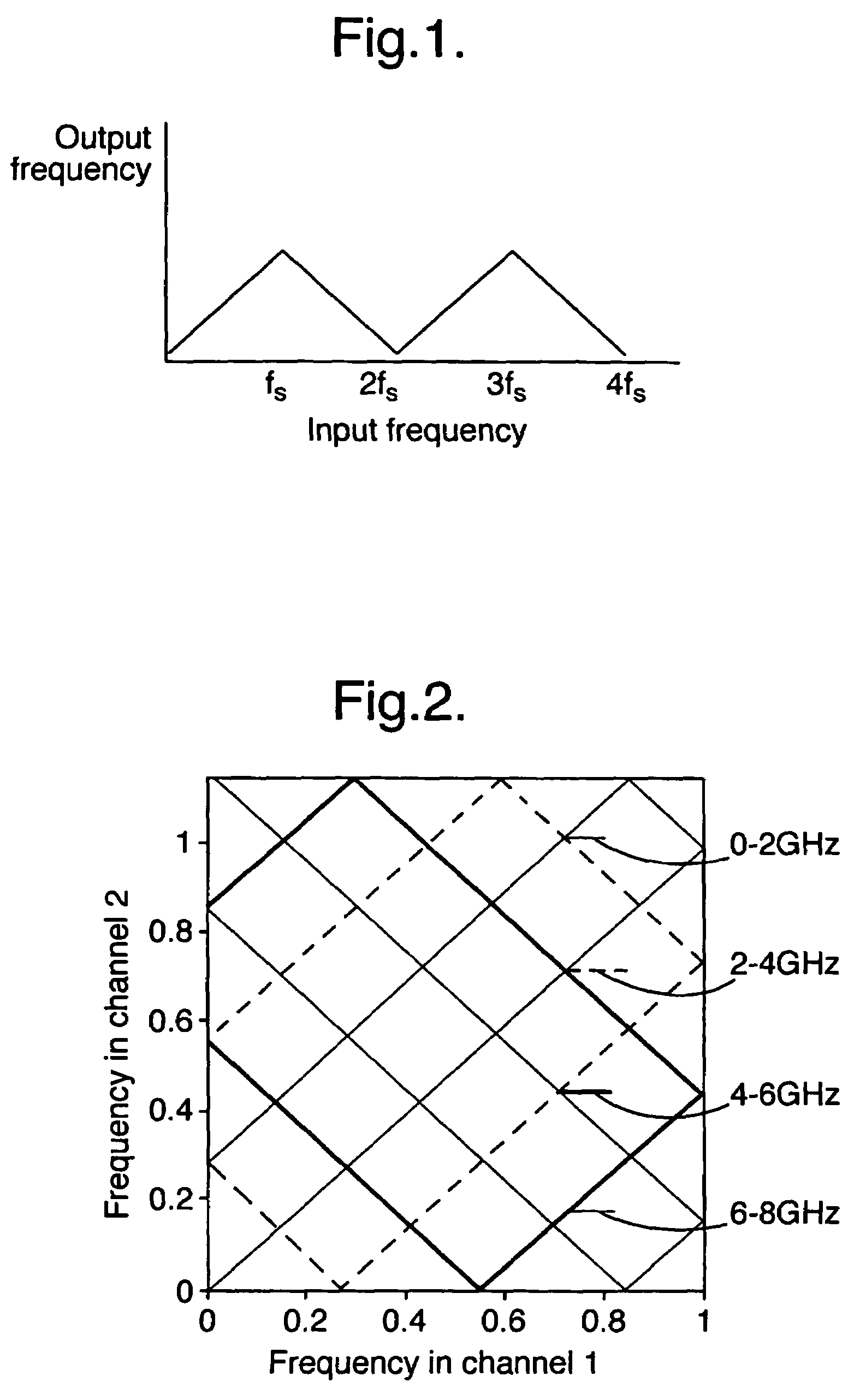
[0035]Turning first to FIG. 1, the sampling frequency is fs. This figure shows that at multiples of this frequency the measured output frequency ‘folds back’ on itself, so that several different input frequencies may give rise to the same output frequency.

[0036]When the same input signal is run at two different clock rates, a known difference in the output signal between the two frequencies is created, which increases at multiples of the sampling frequency. FIG. 2 plots the frequency measured in each of two channels as the input frequency increases, starting at the origin, and moving around the diagram in an anti-clockwise spiral, reflecting off the main axes as shown. All lines have slope +1 or −1 Where the gradient is +1, the relationship between the two frequencies is characterised by a common difference, and likewise, where the gradient is −1, the two frequencies sum to a constant value. The sub-band from which the signal originated can be recognised by identifying the known set...


PUM


Abstract

An apparatus for characterising an input signal within abroad frequency band by comparing the same input signal in a plurality of channels, in order to operate digital Electronic Support Measures (ESM) which require a broad bandwidth to function. The apparatus comprises one or more signal input bands spread across the broad frequency band, a means of splitting the input signal in each input band into a plurality of separate channels, and a means of sampling each channel, wherein the sampling means in each channel runs at a different clock rate from sampling means in each of the other channels within the input bands, so as to remove the ambiguities inherent in frequency aliasing.

Description

CROSS REFERENCE TO RELATED APPLICATIONS[0001]This application is the U.S. national phase of International Application No. PCT / GB2004 / 001911 filed on Apr. 30, 2004 published in English on Nov. 11, 2004 as International Publication No. WO 2004 / 097450 A1, which application claims priority to Great Britain Application No. 0309807.6 filed on Apr. 30, 2003, the contents of which are incorporated by reference herein.FIELD OF THE INVENTION[0002]This invention relates to the field of digital electronics and particularly to signal processing in Electronic Support Measures (ESM) for Radar Systems.BACKGROUND OF THE INVENTION[0003]ESM is the term given to the electronic procedures involved with detecting and identifying a threat and other electromagnetic signals as part of a military platform's defensive capabilities. ESM operates passively, and detects radar signals over a broad frequency range, typically over the band 0.5 to 18 GHz. ESM combines several processes in order to operate effectivel...

Claims


Application Information

Patent Timeline
Patent Type & Authority Patents(United States)
IPC IPC(8): G01S7/40G01S7/02G01S13/00H03D3/00
CPCG01S7/021H03D3/006
Inventor BEHARRELL, GEORGE PETER
Owner THE SEC OF STATE FOR DEFENCE IN HER BRITANNIC MAJESTYS GOVERNMENT OF THE UK OF GREAT BRITAIN & NORTHERN IRELAND
Why Eureka
Try Eureka