Diffractive grating element for balancing diffraction efficiency

Active Publication Date: 2009-01-27
MAGIC LEAP
View PDF21 Cites 88 Cited by
  • Summary
  • Abstract
  • Description
  • Claims
  • Application Information

AI Technical Summary

Benefits of technology

[0020]The main purpose of the current invention is to present a novel solution for decreasing or eliminating completely the above explained angular dependency of the diffraction efficiency in a diffractive grating element. The invention is especially suitable for beam expansion purposes for example in EPEs and virtual display devices. A specific aim of the invention is to make possible to construct biocular and also monocular virtual display systems, where light can be uniformly distributed over the whole area of the exit pupil of the display in order to achieve high image quality.
[0021]To attain these purposes, a device comprising a waveguiding substrate and a diff

Problems solved by technology

However, prior art solutions for EPEs based on the use of holographic/diffractive grating elements (HOEs, or DOEs, i.e. diffractive optical elements) have certain significant limitations, which in practice degrade the quality of the reproduced virtual images.
One of these limitations is the fa

Method used


Image

  • Diffractive grating element for balancing diffraction efficiency
  • Diffractive grating element for balancing diffraction efficiency
  • Diffractive grating element for balancing diffraction efficiency

Examples


Example

[0043]It is to be understood that the drawings presented herein below are designed solely for purposes of illustration and thus, for example, not for showing the various components of the devices in their correct relative scale and / or shape. For the sake of clarity, the components and details which are not essential in order to explain the spirit of the invention have been omitted in the drawings.

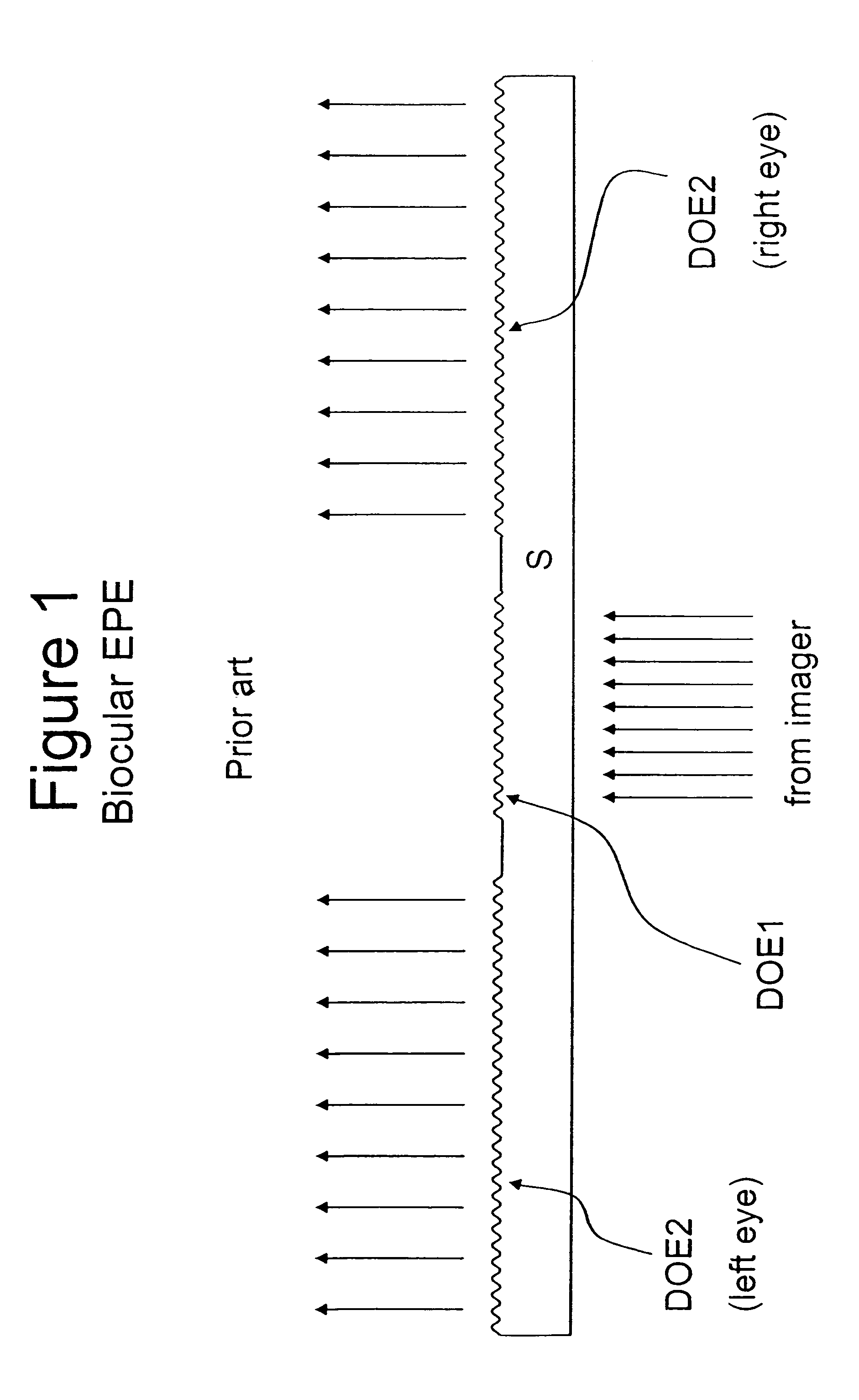
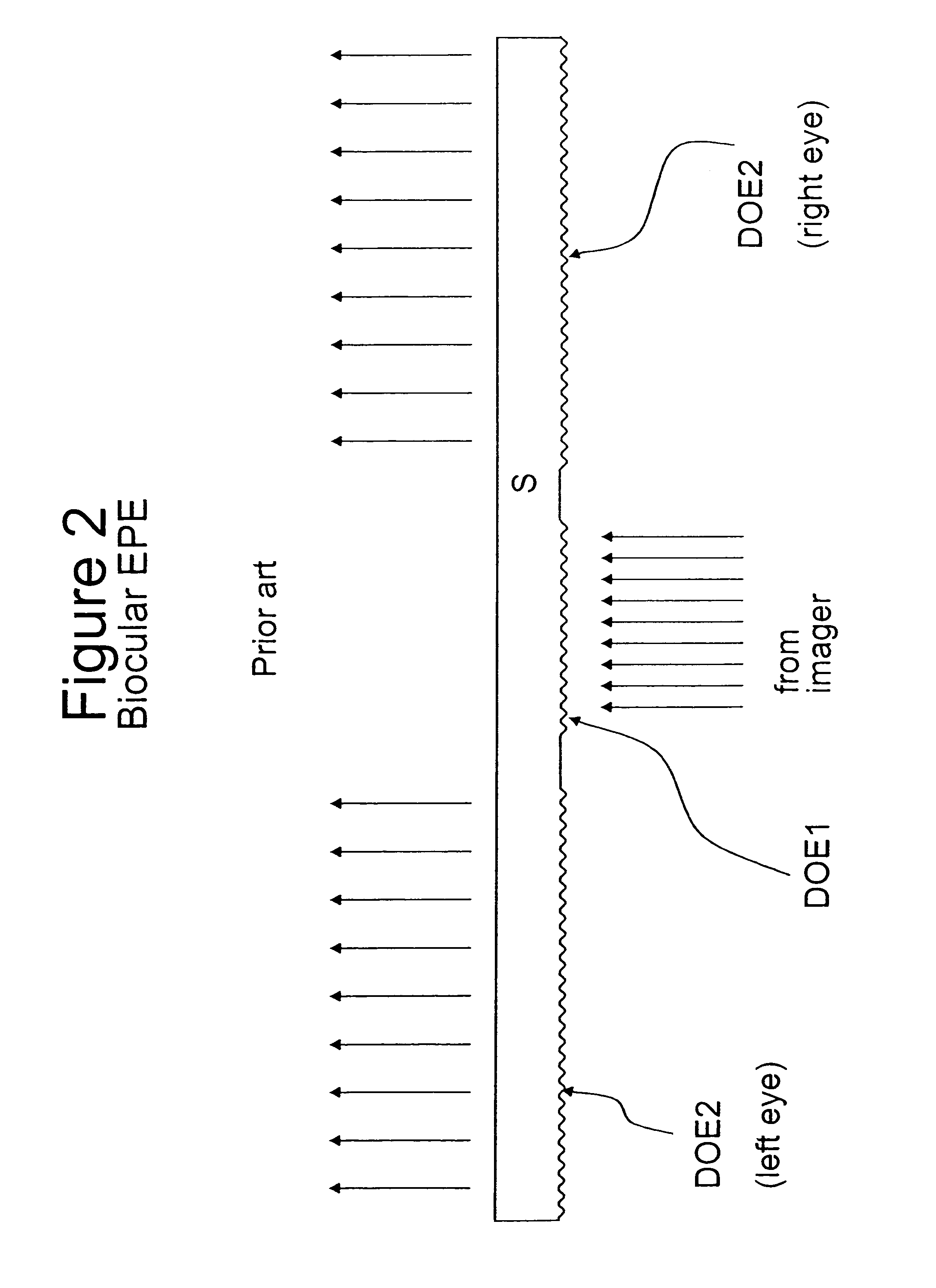
[0044]FIGS. 1-5, which present solutions known from the related art, have been already discussed above.

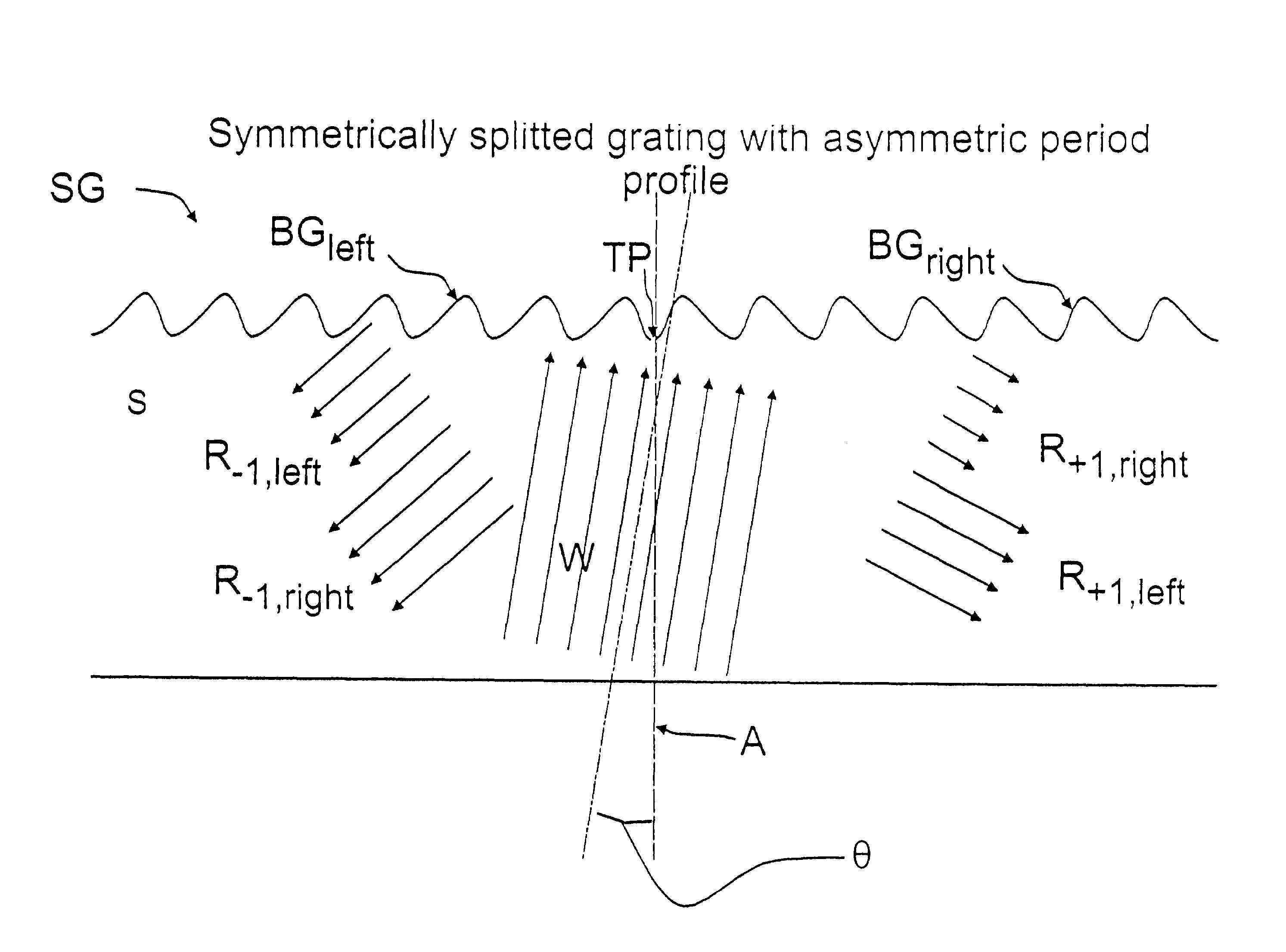
[0045]FIG. 6 illustrates schematically a preferred embodiment according to the invention. A grating profile with asymmetrical period profile, in this particular example with a blazed period profile, is splitted symmetrically with respect to a transition point TP into left BGleft and right BGright sides to form a splitted grating element SG. The left BGleft and right BGright sides of the grating are mirror images of each other with respect to said transition point TP. The transition point T...


PUM


Abstract

A diffractive grating element is divided into at least two different grating regions each having different diffractive properties and arranged on opposite sides with respect to a transition point to form a splitted grating structure. The diffractions generated by the at least two different grating regions are arranged to mutually compensate for the variation in the input angle of the incident light wave to the total diffraction efficiency of the at least one diffracted light wave that is arranged to propagate within the substrate.

Description

CROSS-REFERENCE TO RELATED APPLICATIONSField of the Invention [0001]This application is the U.S. National Stage of International Application Number PCT / FI2003 / 000948 filed Dec. 12, 2003, published in English Jul. 1, 2004, under International Publication Number WO 2004 / 055556 and which claims priority to Finnish Patent Application No. 20022199 filed on Dec. 16, 2002.[0002]The present invention relates to a diffractive grating element arranged on or embedded within a light-transmittive, preferably planar waveguiding substrate and arranged to interact with an incident light wave in order to couple the energy from said incident light wave into said substrate to form at least one diffracted light wave propagating within said substrate and corresponding to at least one selected diffraction order.BACKGROUND OF THE INVENTION[0003]Display technology is one of the key elements in the development of new portable devices, which today typically feature wireless connectivity for voice and data ac...

Claims


Application Information

Patent Timeline
IPC IPC(8): G02B6/30G02B5/18G02B5/32G02B6/12
CPCG02B5/1842G02B5/32G02B27/0081G02B2006/12107G02B27/0944
Inventor LEVOLA, TAPANI
Owner MAGIC LEAP
Why Eureka
Try Eureka