Implantation system for annuloplasty rings

a technology of annuloplasty and ring, which is applied in the field of prosthetic annuloplasty ring systems, can solve the problems of incompetence, narrow diseased valves, inability to repair, etc., and achieve the effects of eliminating the risk of over-correction, improving hemodynamic functioning, and improving coaptation of leaflets

Inactive Publication Date: 2009-02-03
QUICKRING MEDICAL TECH LTD
View PDF27 Cites 1252 Cited by
  • Summary
  • Abstract
  • Description
  • Claims
  • Application Information

AI Technical Summary

Benefits of technology

[0011]The invention provides implantation systems and methods for implanting annuloplasty rings or the like which not only can be accomplished in a reduced time period but which are effective to achieve better coaptation of the leaflets following implanta

Problems solved by technology

Diseased valves may become narrow, incompetent or both.
A great many patients suffering from ischemic heart disease, who previously underwent myocardial infarctions, consequently develop various degrees of mitral valve incompetence.
Typically in those patients, the valve may grossly seem to be normal; yet its annulus is dilated, causing coaptation or interengagement of the leaflets to be disturbed and resulting in incompetence of the valve.
Carpenter's method could significantly improve valve function, some surgeons believe that the rigid structure of rings of this type may compromise the natural flexibility of the valve components.
Although flexible rings may avoid constraining the natural flexibility of the annulus while still improving valve function, there are some disadvantages in using flexible rings.
For example, when the suture

Method used


Image

  • Implantation system for annuloplasty rings
  • Implantation system for annuloplasty rings
  • Implantation system for annuloplasty rings

Examples


Embodiment Construction

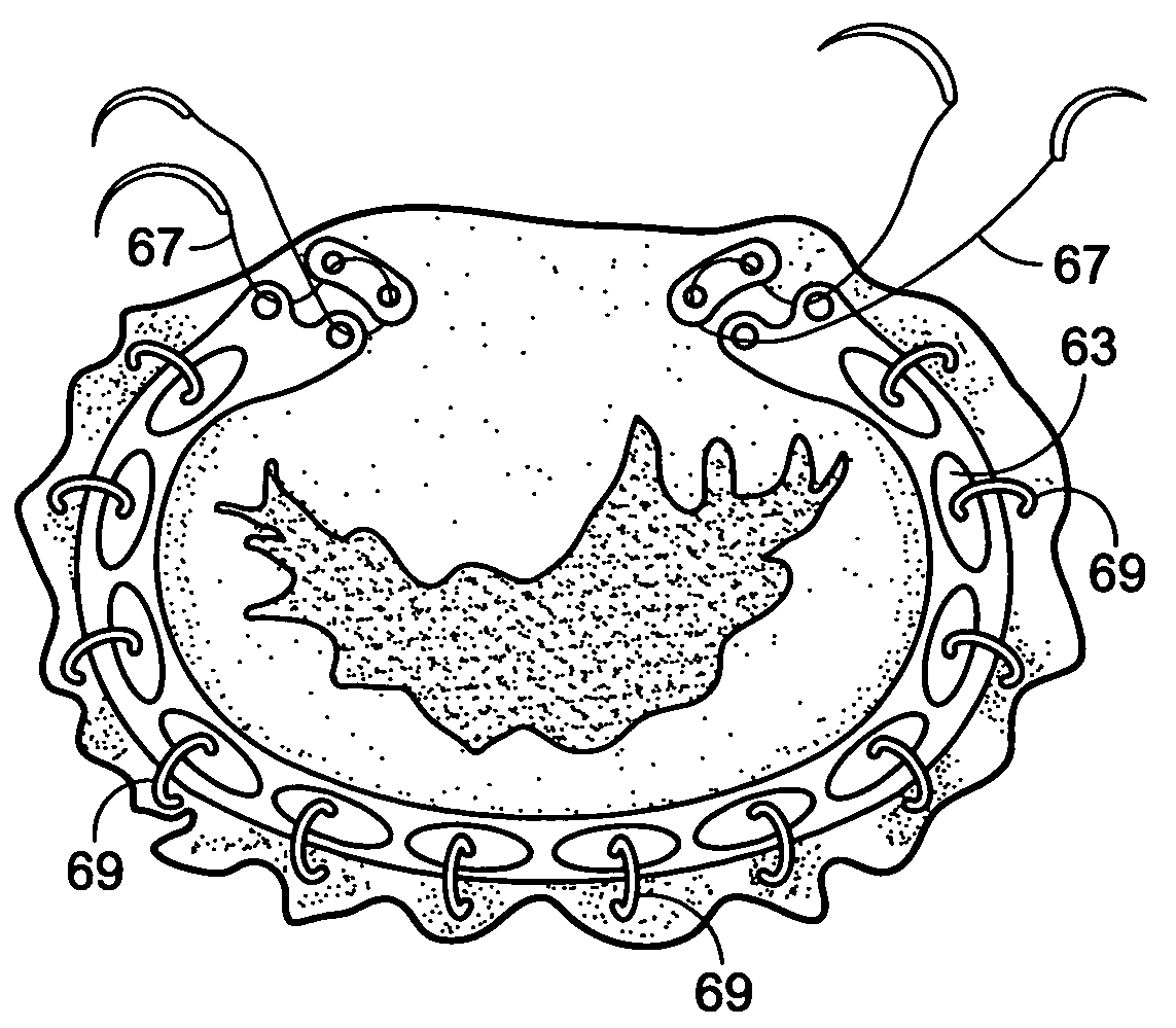
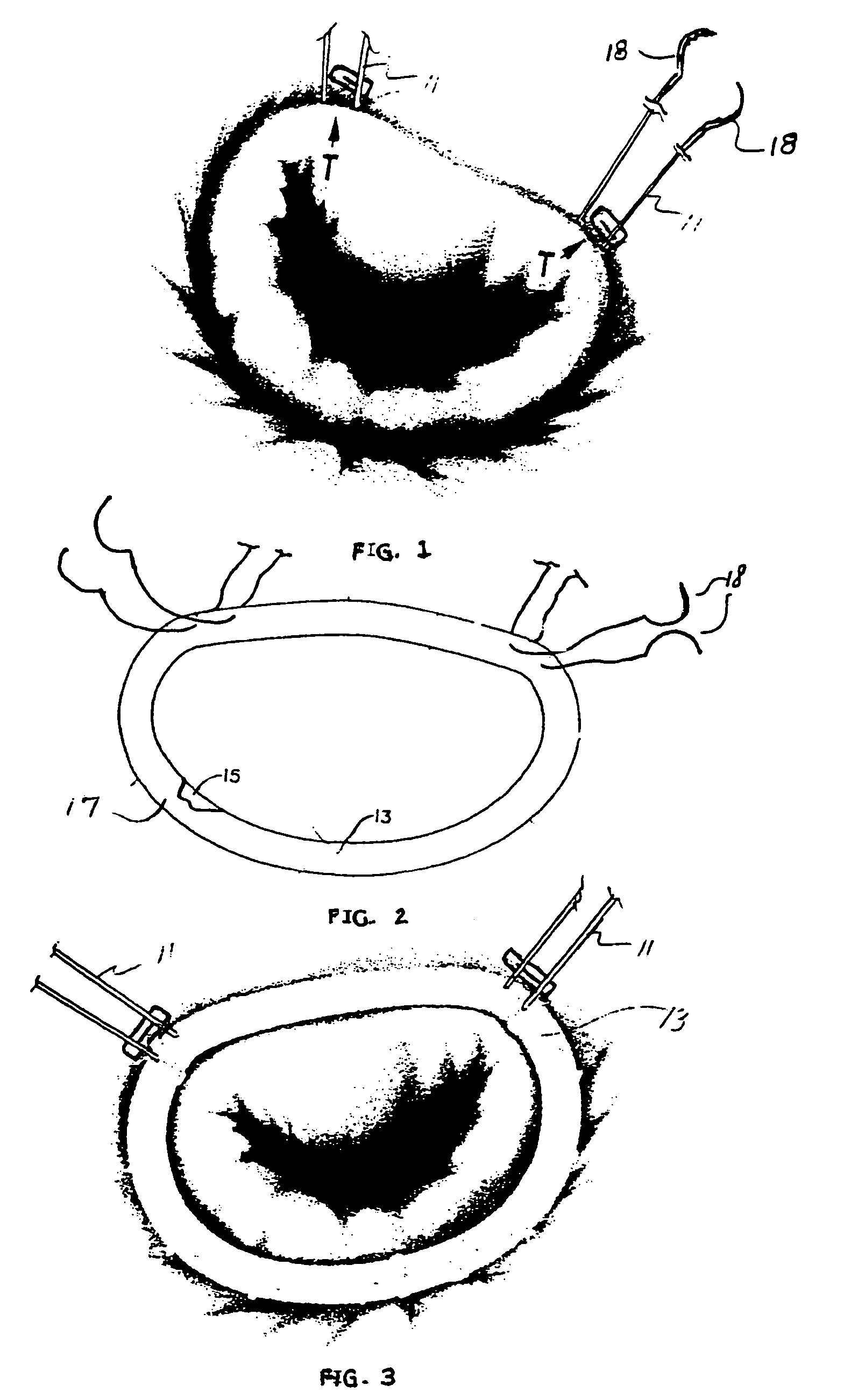
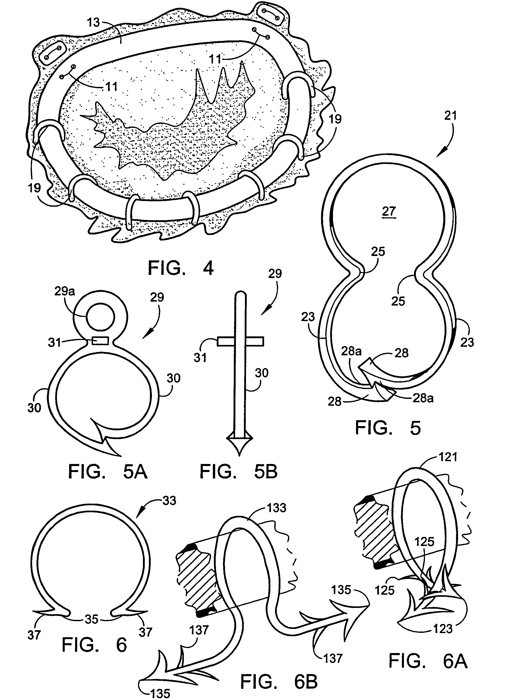
[0061]It has been found that, through the use of supports, such as staples and preferably staples of a preferred design, an improved annuloplasty system can be created that can be installed, for example, with the use of only two U-shaped, pledgetted trigonal sutures, in less than one-half the time it presently takes to install the present generation of annuloplasty rings. For purposes of this application, the term “annuloplasty ring” is intended to include complete generally D-shaped rings as well as open rings or bands that may have a generally C-shape and which are rigid or flexible; in any event, an annuloplasty ring system which is used will be proportioned so as to reconfigure an atrioventricular heart valve that has become incompetent or in some other way defective.

[0062]Heretofore, the incorporation of an annuloplasty ring has involved an operation that generally required about as much time in surgery as an actual total valve replacement. However, using the present invention,...


PUM


Abstract

Methods for reconfiguring an atrioventricular heart valve that may use systems comprising a partial or complete annuloplasty rings proportioned to reconfigure a heart valve that has become in some way incompetent, a pair of trigonal sutures or implantable anchors, and a plurality of staples which may have pairs of legs that are sized and shaped for association with the ring at spaced locations along its length. These systems permit relative axial movement between the staples and the ring, whereby a patient's heart valve can be reconfigured in a manner that does not deter subtle shifting of the native valve components. Shape-memory alloy material staples may have legs with free ends that interlock following implantation. Annuloplasty rings may be complete or partial and may be fenestrated. One alternative method routes a flexible wire, preferably of shape-memory material, through the bights of pre-implanted staples. Other alternative systems use linkers of shape-memory material having hooked ends to interengage with staples or other implanted supports which, following implantation, decrease in effective length and pull the staples or other supports toward one another so as to create desired curvature of the reconfigured valve. These linkers may be separate from the supports or may be integral with them and may have a variety of shapes and forms. Various of these systems may be implanted non-invasively using a delivery catheter.

Description

[0001]This application is a continuation-in-part of PCT / IB02 / 05570, filed Dec. 19, 2002, which claims priority from U.S. Provisional Application Ser. No. 60 / 342,824 filed Dec. 21, 2001. The disclosures of both applications are incorporated herein by reference.FIELD OF THE INVENTION[0002]This invention relates to prosthetic annuloplasty ring systems designed to surgically correct defects in heart valves and more particularly to method and systems for the efficient and effective implantation of corrective rings and the like.BACKGROUND OF THE INVENTION[0003]Rheumatic, connective tissue or ischemic heart diseases may heavily affect the configuration of the atrioventricular heart valves. Diseased valves may become narrow, incompetent or both. A great many patients suffering from ischemic heart disease, who previously underwent myocardial infarctions, consequently develop various degrees of mitral valve incompetence. Typically in those patients, the valve may grossly seem to be normal; ye...

Claims


Application Information

Patent Timeline
IPC IPC(8): A61F2/24A61B17/00A61B17/04A61B17/06A61B17/064
CPCA61B17/0401A61B17/064A61B17/0644A61F2/2448A61B2017/00783A61B2017/00867A61B2017/0404A61B2017/0412A61B2017/0414A61B2017/0427A61B2017/0464A61B2017/0472A61B2017/06057A61B2017/0641A61B2017/0647
Inventor MILO, SIMCHA
Owner QUICKRING MEDICAL TECH LTD
Why Eureka
Try Eureka