
Integrative and real-time radiation measurement methods and systems

a radiation measurement and real-time technology, applied in the field of ionizing (nuclear) radiation detection, can solve the problems of fading of osl signals, detectors cannot distinguish between chronically- and acutely-delivered doses, and stored signals in tl detectors tend to “fade”

Inactive Publication Date: 2009-02-03
RGT UNIV OF MICHIGAN
View PDF10 Cites 39 Cited by
  • Summary
  • Abstract
  • Description
  • Claims
  • Application Information

AI Technical Summary

Benefits of technology

The patent text discusses the need for a system to detect and prevent the use of radioactive materials in a populated area, as well as the movement of such materials for intelligence gathering and forensic purposes. The technical effects of the patent include the development of a network of radiation detection devices that can intercept and monitor the movement of radioactive materials, as well as affordable technology to perform this function. The system can also be used for intelligence gathering and forensic purposes, and can help track a terrorist who sets off a dirty bomb or uses a portable radiation-producing device to expose a population. The patent also mentions the use of passive dosimeters for personnel dosimetry and the need for affordable technology to perform comprehensive screening of cargo and to detect and prevent the use of radioactive materials in real-time operation and accidents.

Problems solved by technology

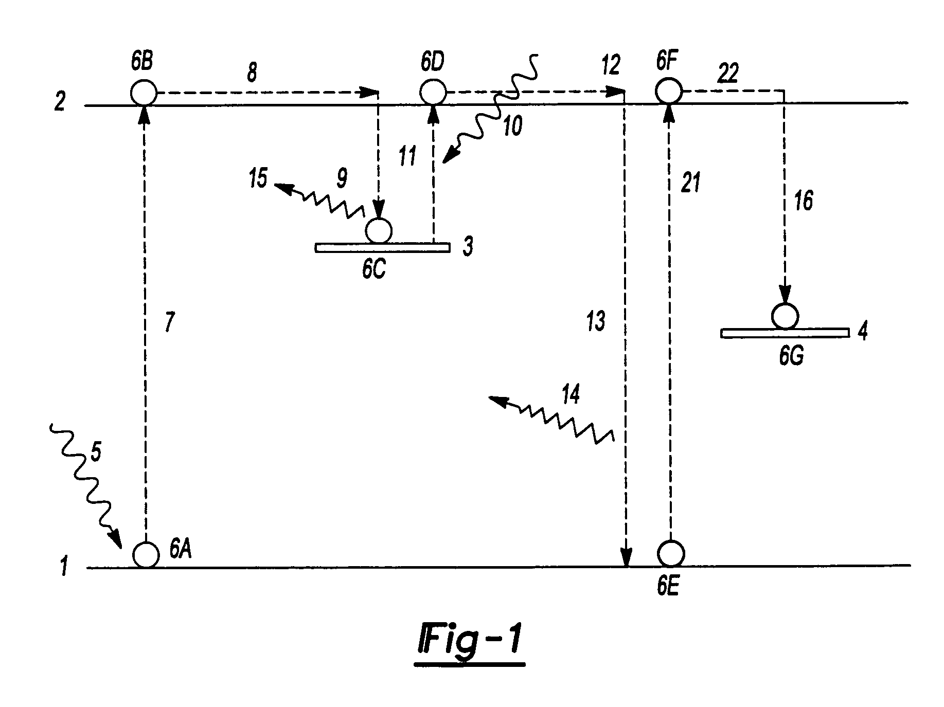
As a result, the stored signal in a TL detector tends to “fade” over time.
Similarly, extraneous light exposure may cause the fading of OSL signals.
These detectors cannot distinguish between chronically- and acutely-delivered doses.
However, it was never broadly implemented.
The single ratio approach is limited in that it does not allow the distinction between a chronic lower-exposure rate dose rate, multiple pulses of radiation, and an acute dose delivered in a single pulse.
This prior approach also does not allow the assumption of other than very simple functions describing fading as a function of time.
In addition, changes in sensitivity of different peaks have been observed at a variety of times post-annealing, and this cannot be taken into account with these simple methods.
These values are not dramatically different, so the accuracy and precision in determining the time of the chronic exposure, especially in the presence of measurement noise, will be limited.
However, if reliance was made upon only a pair of peaks or signals from materials having different peak fading rates, then an error in a single reading can cause the system to be unreliable.
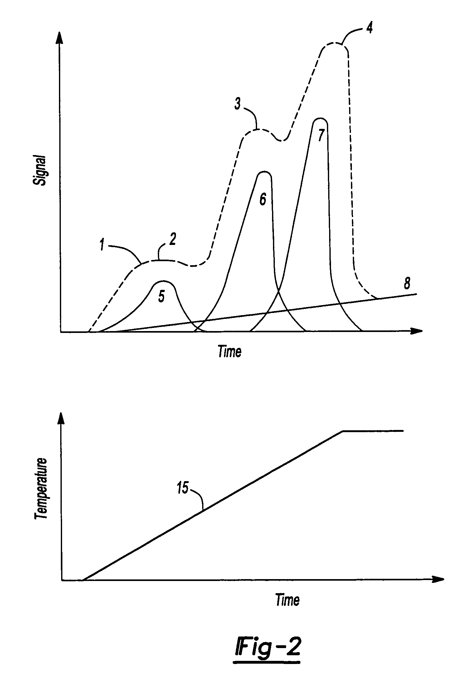
However, in many materials, there is overlap between the peaks.
This complicates analysis or separation of the individual peaks.
These are of continuing concern to the users of TLDs and will confound the practical implementation of temporal dosimetry methods that employ them.
Both should give the same results, and variations between them can be due to excessively high temperatures, unusual conditions of humidity, exposure of the materials to bright light of specific wavelengths, other extreme environmental conditions or tampering.
Because these functions may be complex, simple solutions may not be possible.
It is likely that matrix methods will be unstable in their practical application, and such over sampling would result in greater numerical stability and confidence in the solution.
Thus data can be obtained without needing to resort to complex numerical glow curve deconvolution and / or curve fitting methods which introduce additional error into the dosimetry methods, potentially rendering temporal dosimetry impractical.
Although separation of all of the peaks completely may not be possible, the separation may be sufficient to enable the method to work adequately without applying the more complex deconvolution methods.
The application of this method and the usage of different materials having simple glow curves noted above may also decrease the importance of the glow curve analysis process
The material that is more slowly fading fails to reach equilibrium quickly.
TL materials lose their signal at more rapid rates at higher temperatures and are not as sensitive to light, whereas OSL materials tend to lose their signals as a result of exposure to light and are not as sensitive to temperature variations.
Lack of a stable solution to the equations may raise suspicion, based upon experience with the overall method, and can form the basis for further inspection of the cargo.
If a constant dose is assumed over the deployment time, then variations in predictions of this dose can also be a cause for suspecting tampering.
If they do not, it can be because of unusual light and heat exposures.
Alternatively, differences can indicate tampering, resulting in flagging of the container.
The actual accumulated signal, however, would be affected by the environmental conditions.
If the detection system is concealed, tampering with it will be made more difficult.
They may, however, result in the deposition of dose if they come in direct contact with a dosimeter.
In reality, the situation is more complicated.
The filtered approach has been limited in application to distinguishing deep dose, shallow dose, and neutron dose from each other and determining the values of these doses.
In addition, smaller differences in thickness will result in larger changes in absorption when lead is used.
At very high doses, however, there may be deviations from this linearity because of saturation of the material traps.
Alternatively, non-uniform doses measured with multiple dosimeters on a single package would indicate a distribution of radioactive source within the package that can be considered suspicious.
Unusual physical distributions of dose can flag cargo as being suspicious because this can indicate the presence of a radioactive point source or another non-uniform radiation distribution within the package.
The incident radiation produces defects in the plastic.
This approach can be used in instances for which complete bleaching of the signal from the dosimeters and thus resetting them would not be possible.

Method used

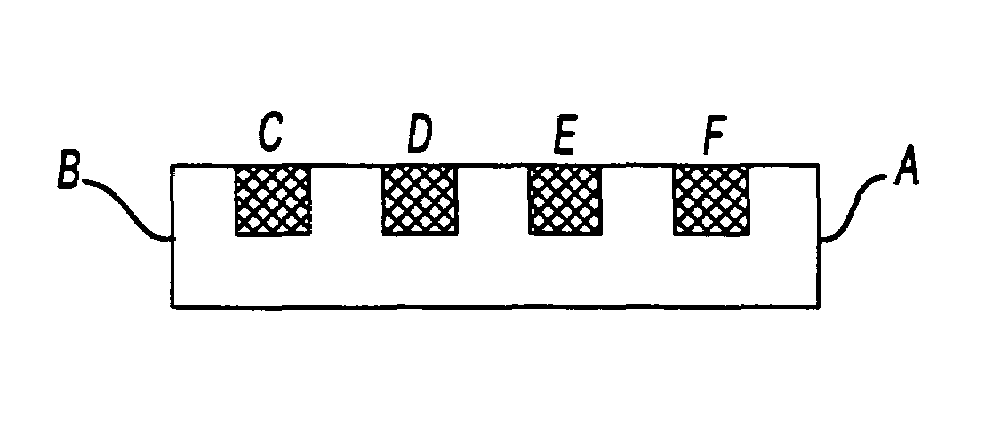

Image

  • Integrative and real-time radiation measurement methods and systems
  • Integrative and real-time radiation measurement methods and systems
  • Integrative and real-time radiation measurement methods and systems

Examples


Embodiment Construction

[0039]The following description is merely exemplary in nature and is not intended to limit the present disclosure, application, or uses.

Desirable Characteristics of Methods and Systems

[0040]One of the most important performance characteristics of a practical radiation detection system is its ability to detect small amounts of radiation, which is often associated with shielded devices. This capability is typically referred to as “sensitivity”. The radiation detection sensitivity for traditional radiation detection systems is determined by the total number of “counts” for some systems or the instantaneous count rate for others. Thus the duration of time during which an object is examined is critical for being able to detect small amounts of radiation.

[0041]While extending observation times is possible in the laboratory environment, it is more difficult in a field environment where the background radiation may be high or changing, and the object may be large in size. Some detectors (fo...


PUM


Abstract

A method of determining the radiation type and energy distribution of a radiation source that outputs radiation. The method including providing a plurality of detector materials and exposing the plurality of detector materials to the radiation. Each of the plurality of detector materials stores a signal in response to being exposed to the radiation. The signals are representative of the radiation. The plurality of detector materials is stimulated to output the signals as measured signals. These measured signals are used to determine the radiation type and energy distribution of the radiation.

Description

CROSS-REFERENCE TO RELATED APPLICATIONS[0001]This application claims the benefit of U.S. Provisional Application No. 60 / 685,740, filed on May 27, 2005. The disclosure of the above application is incorporated herein by reference.FIELD[0002]The present disclosure relates to methods and systems for the detection of ionizing (nuclear) radiation, identification of the isotopic, and other sources of such radiation, and determination of the time when such radiation was observed. More particularly, the present disclosure relates to methods and systems for preparation of systems employing dosimetric materials and methods of analysis of the data they collect to determine both the nature and extent of radiation to which they were exposed and the temporal information allowing determination of the duration and time of exposure.BACKGROUND AND SUMMARY[0003]The statements in this section merely provide background information related to the present disclosure and may not constitute prior art.[0004]A...

Claims


Application Information

Patent Timeline
Patent Type & Authority Patents(United States)
IPC IPC(8): H05B33/00
CPCG01T1/10G01T1/11
Inventor KEARFOTT, KIMBERLEE J.
Owner RGT UNIV OF MICHIGAN
Learn More